Infusion flow regulator, infusion flow regulating set, and infusion flow regulating method

a flow regulator and flow regulating technology, applied in the direction of flow monitors, intravenous devices, medical syringes, etc., can solve the problems of deteriorating the accuracy of flow rate regulation, medical accidents, inaccuracy in measuring flow rate, etc., to prevent time delay and measurement error, and quick and accurate flow regulation

Inactive Publication Date: 2014-06-03
HANVIT MD +1
View PDF7 Cites 1 Cited by
  • Summary
  • Abstract
  • Description
  • Claims
  • Application Information

AI Technical Summary

Benefits of technology

[0024]According to the present invention, among various factors for determining a flow rate at an initial treatment stage, only the tuning of the manipulation unit is a variable parameter, and all the other factors are reflected and fixed at the initial stage of the treatment. As a result, specific flow rates at the reference point, each of which is tailored to a patient's condition and situation, can be calculated, and flow rate can be tuned through a single tuning of the manipulation unit in accordance with a relative flow rate ratio in relation to the reference point in a predetermined functional relationship established only by the tuning of the manipulation unit, which is the only variable parameter. Consequently, the flow rate can be quickly and accurately regulated through a single tuning of the manipulation unit without being affected by other variable factors.
[0025]In accordance with the present invention, a single measurement of flow rate at the reference point is sufficient for regulating the flow rate without needing to repeatedly measure the flow rate. As a result, the inventive infusion regulator allows quicker flow regulation as compared to a conventional infusion flow regulator, of which flow rate must be measured repeatedly while moving a manipulation unit for flow regulation.
[0026]As a result, the present invention can prevent a medical accident which has occurred due to inaccurate flow regulation caused by a conventional infusion flow regulator, on which flow rate values are indicated as absolute values although the flow rate is affected by the installation environment of the infusion flow regulator. In addition, the present invention can prevent time delay and measurement error which have been caused in the prior art due to the necessity of repeatedly measuring flow rate whenever the conventional infusion flow regulator is manipulated. Moreover, since the inventive infusion flow regulator can be easily used by a beginner or an un-skilled person, the delivery of an infusion solution can be performed more efficiently.

Problems solved by technology

However, the infusion flow regulator 15 shown in FIG. 1 has a disadvantage in that since the flow rate should be measured while seeing the drip chamber 12 whenever the roller type manipulation unit 15a is stopped at a point, complicated measurements should be repeatedly performed, which will deteriorate the accuracy of flow rate regulation.
A problem herein may occur when a person responsible for regulating the flow rate of an infusion solution in accordance with a prescribed order trusts the flow regulation capability of such an infusion flow regulator after the infusion set is installed despite of the disadvantage of such an infusion flow regulator as described above.
In such a case, the person may misjudge that the infusion flow regulator has been tuned to the prescribed flow rate, which may in turn cause a medical accident.
In such a case, a problem may occur due to inaccuracy in measuring flow rate in the process of repeatedly measuring the flow rate.
Moreover, such inaccurate tuning of the flow rate makes it difficult to correctly determine when the infusion solution contained in the infusion solution bottle is completely consumed.
As a result, the infusion set may not be timely separated from the patient at the time when the infusion solution is completely consumed, or the emptied liquid solution bottle may not be replaced by a new one, which may in turn cause a medical accident.
However, there is a problem in that the manipulation unit 15a of the infusion flow regulator 15 should be continuously manipulated until the drops' falling interval becomes matched with that of the sounds.

Method used


Image

  • Infusion flow regulator, infusion flow regulating set, and infusion flow regulating method
  • Infusion flow regulator, infusion flow regulating set, and infusion flow regulating method
  • Infusion flow regulator, infusion flow regulating set, and infusion flow regulating method

Examples


first embodiment

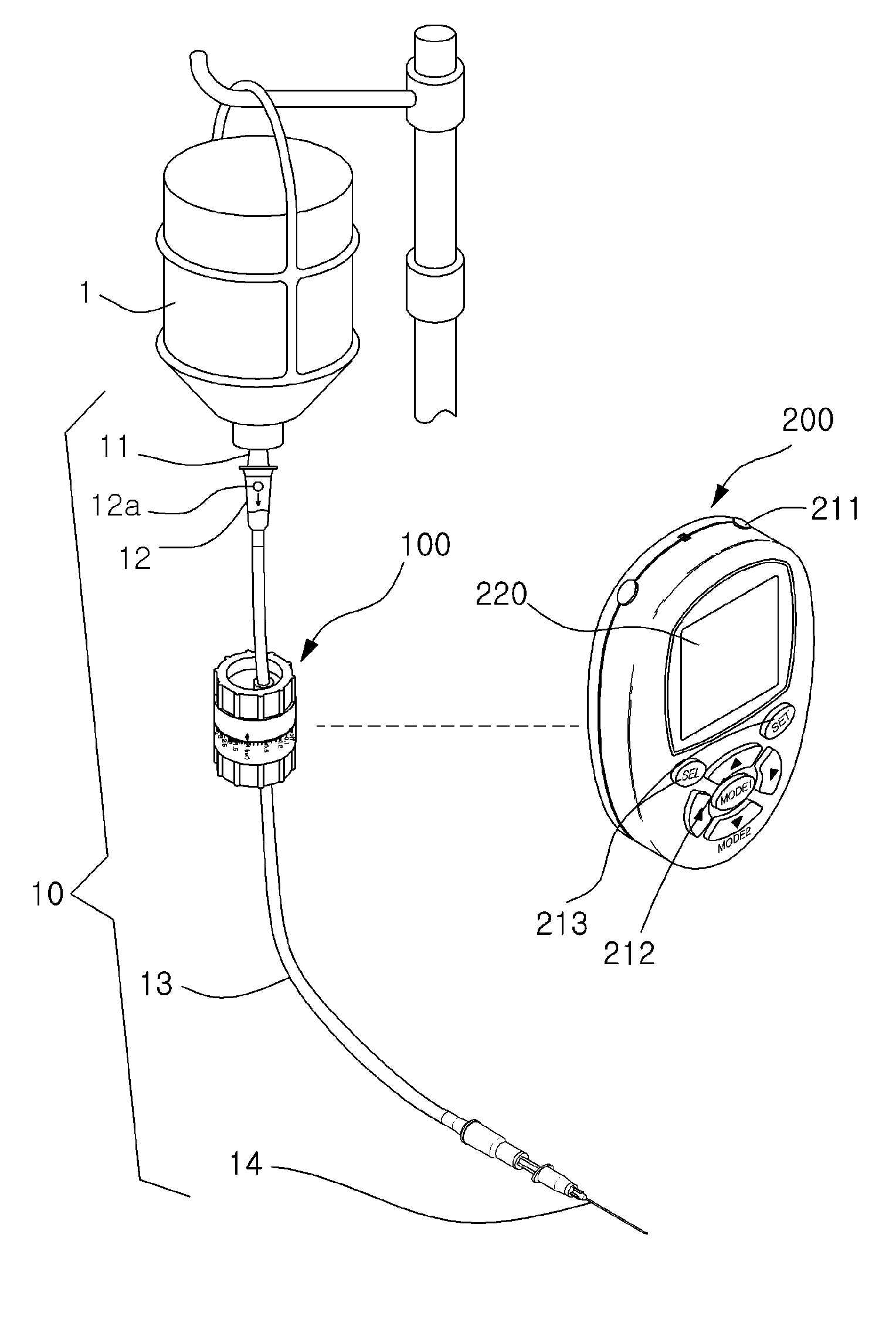
[0041]FIG. 3 shows an infusion flow regulator 100 in accordance with the present invention, in which the present invention is applied to an IV flow regulator type infusion flow regulator.

[0042]Briefly describing an IV flow regulator type infusion flow regulator, which is well-known in the art, it includes a manipulation unit 110 rotatably mounted on the body 140 of the regulator, and a tube connected to the manipulation unit 110 and the body 140 at opposite ends thereof, so that an infusion solution is allowed to pass between the ends of the tube, wherein the flow rate of the infusion solution can be regulated in accordance with the rotated angle of the manipulation unit 110. Since such an IV flow regulator type infusion flow regulator is not limited to the type shown in FIG. 3, and can be fabricated in various types including that shown in FIG. 2b, it shall be noted that the embodiments of the present invention described below can be applied to any of various IV flow regulator type...

second embodiment

[0051]FIG. 4 is a perspective view of an infusion flow regulator in accordance with the present invention.

[0052]Although the second embodiment shown in FIG. 4 is applied to an IV flow regulator type infusion flow regulator like the first embodiment as described above, the second embodiment is different from the first embodiment in that the scales 130 are marked in an equal scale interval with reference to the reference point 120, and the numerical values 131, which are given to some of the scales 130 due to the area occupied by the numerical values, are also marked to be proportional to the distances from the reference point 120, respectively. In other words, the scales 130 and the numerical values 131 are marked in the same method as a method of marking scales and numerical values on a measuring tape for measuring a length. The numerical values 131 in the embodiment shown in FIG. 4 are values increasing in proportion to the distances from the reference point 120, wherein the values...

third embodiment

[0055]FIG. 5 is a perspective view of an infusion flow regulator in accordance with the present invention.

[0056]Although the third embodiment is applied to an IV flow regulator type infusion flow regulator like the first and second embodiments described above, the infusion flow regulator applied in the third embodiment is different from the first and second embodiments in that it is applied to an IV flow regulator type infusion flow regulator which is fabricated to regulate flow rate in proportion to the rotated angle of the manipulation unit 110. As such, the third embodiment indicates the scales marked with reference to the reference point 120 in an equal interval, and also indicates the numerical values given to the scales as the ratios of flow rates at individual scales in relation to the flow rate at the reference point, in which the indicated numerical values are values which are increasing in proportion to the distances from the reference point, respectively.


PUM


Abstract

Disclosed is an infusion flow regulator, in which a reference point is set within a manipulating range of a manipulation unit for regulating a flow rate in the infusion flow regulator, so that a manipulating point of the manipulation unit can be tuned with reference to the ratio of a flow rate measured at the reference point in relation to a prescribed injection flow rate, whereby the flow rate can be quickly and accurately tuned to the prescribed flow rate. The disclosure also includes an infusion flow regulating set including the infusion flow regulator, and an infusion flow regulating method using the same.

Description

TECHNICAL FIELD[0001]The present invention relates to an infusion flow regulator, in which a reference point is set within a manipulating range of a manipulation unit for regulating flow rate in the infusion flow regulator, so that a manipulating point of the manipulation unit can be tuned with reference to the ratio of a flow rate measured at the reference point in relation to a prescribed flow rate for injection, whereby the flow rate can be quickly and accurately matched to the prescribed flow rate. The present invention also relates to an infusion flow regulating set including such an infusion flow regulator, and an infusion flow regulating method using the same.BACKGROUND ART[0002]As shown in FIG. 1, an intravenous (IV) system for delivering an infusion solution into a vein includes: an infusion solution bottle 1, in which the infusion solution is contained; an insertion spike 11 adapted to be inserted through a sealing plug of the infusion solution bottle 1 to allow the infusi...

Claims


Application Information

Patent Timeline
Patent Type & Authority Patents(United States)
IPC IPC(8): A61M5/00
CPCA61M5/172A61M5/16886A61M5/16804
Inventor LEE, DOO-YONG
Owner HANVIT MD
Why Eureka
Try Eureka