Vacuum regulating valve

a vacuum pressure and valve body technology, applied in the direction of bridges, instruments, fluid pressure control, etc., can solve the problems of high driving force against the stopper, piston compression thereby at high driving force, and the inability to quickly and accurately regulate the opening, etc., to achieve quick and accurate control, high controllability, and vacuum pressure

Active Publication Date: 2006-10-10
SMC CORP
View PDF4 Cites 39 Cited by
  • Summary
  • Abstract
  • Description
  • Claims
  • Application Information

AI Technical Summary

Benefits of technology

[0011]Accordingly, the present invention is to provide a highly controllable vacuum regulating valve capable of perform quick and accurate control of the opening of a valving member, thereby enabling vacuum pressure in a vacuum chamber to be quickly and accurately regulated.
[0012]In addition, the invention is to enable a stopper for setting a stop position of a piston for driving a valving member to be driven by a small and inexpensive electric motor, thereby to provide a vacuum regulating valve having high economical efficiency.
[0018]In the vacuum regulating valve having the above-described configuration, the main controller performs a comparison between the pressure signal from the pressure sensor and the given pressure set value, thereby to output the signal indicative of the stopper position for appropriately setting the opening of the valving member to the motor controller which controls the driving of the electric motor, and outputs the control signal being used to control the fluid pressure in the pressure receiving chamber to be the pressure necessary for the solenoid valve. Thereby, the electric motor is rotated forward or backwards to move the stopper to a specified position. In addition, the pilot fluid is supplied to the pressure receiving chamber from the solenoid valve, and the piston is moved to a position where being compressed into abutment with the stopper in opposition to the resilience of the piston 32, whereby a valve opening necessary for the valving member is imparted. The valve opening can be substantially steplessly regulated in accordance with the rotation angle of the electric motor. In addition, the valving member can be opened using the resilience of the return spring in the manner that the pilot fluid in the pressure receiving chamber is discharged and thereby reduced.
[0019]In the vacuum regulating valve, the stopper is moved to be accurately positioned by using the electric motor, and the piston is compressed to abut the stopper to control the operation position of the piston. Thereby, the valving member can be quickly and accurately positioned through quick and accurate positioning of the stopper enable the opening of the valving member to be accurately controlled, so that the vacuum regulating valve has high controllability, and the vacuum pressure in the vacuum chamber can be accurately regulated. Further, since the electric motor is used only for the positioning of the stopper, a small and inexpensive electric motor can be used for the electric motor, whereby the vacuum regulating valve can be enhanced in power saving consumption and miniaturization, and is therefore made excellent in economical efficiency.
[0024]With the above-described function imparted to the main controller, the electric motor can be a very small and inexpensive motor only for positioning the stopper, whereby the vacuum regulating valve can be enhanced in power saving consumption and miniaturization, and is therefore made excellent in economical efficiency.
[0025]According to the vacuum regulating valve having the above-described configuration according to the invention, it is possible to obtain a vacuum regulating valve having high controllability wherein the opening of a valving member can be quickly and accurately controlled, whereby the vacuum pressure in the vacuum chamber can be quickly and accurately controlled. Further, driving of the stopper being used to set the stop position of a piston being used to control the valving member can be implemented by using a small and inexpensive electric motor. Consequently, the vacuum regulating valve having high economical efficiency can be obtained.

Problems solved by technology

However, such a vacuum valve is not inherently intended for regulating the vacuum pressure (negative pressure) in a vacuum chamber through the opening of such a valving member.
Even if attempt was made to regulate the opening of the valving member, the opening would not be able to be quickly and accurately regulated.
However, the piston is compressed thereby at high driving force against the stopper.
In addition, it is difficult to drive the stopper under the effects of the driving force by using a small electric motor, so that countermeasures therefor have to be taken into consideration.

Method used


Image

  • Vacuum regulating valve
  • Vacuum regulating valve

Examples


Embodiment Construction

)

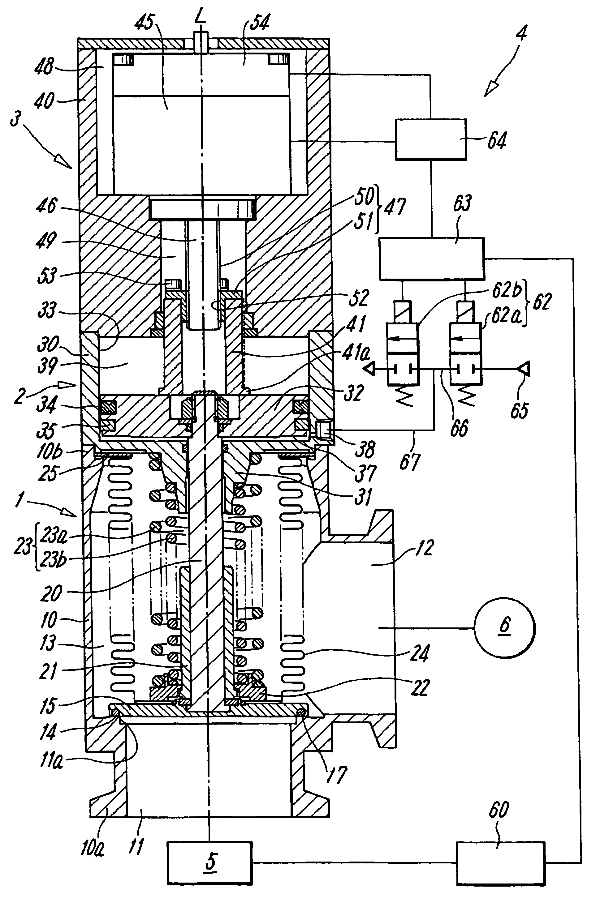
[0028]FIG. 1 is a view showing a representative preferred embodiment of a vacuum regulating valve according to the present invention. The valve is configured to include a valve main body section 1 including a valving member 15 that opens and closes a flowchannel 13 between main ports 11 and 12; a cylinder section 2 that is used for open and close operation of the valving member 15; a valve-opening regulating section 3 that sets the opening of the valving member 15; and a valve control section 4 that controls the opening of the valving member 15 in accordance with an output of a pressure sensor 60 that detects the pressure in the valving member 15. The valve main body section 1, the cylinder section 2 and the valve-opening regulating section 3 are series connected together along an axis L of the valve.

[0029]The valve main body section 1 includes a hollow valve housing 10 substantially having a round columnar or angular columnar shape. The valve housing 10 is provided with a first ma...


PUM


Abstract

A vacuum regulating valve has high controllability, wherein the opening of a valving member can be quickly and accurately controlled by using a small and inexpensive electric motor. In accordance with a signal indicative of a pressure set value and a pressure signal from the pressure sensor, the main controller in the valve control section outputs a signal for setting the opening of the valving member to a motor controller that controls the electric motor, and performs control to cause a pilot fluid to be supplied to a pressure receiving chamber of the piston, thereby causing the piston to move to the position of abutment with the stopper.

Description

BACKGROUND OF THE INVENTION[0001]1. Field of the Invention[0002]The present invention relates to a vacuum regulating valve for the use of, for example, creating a pressure reduction in a chemical-reaction vacuum chamber included in a physical or chemical machine or the like.[0003]2. Description of the Related Art[0004]In a semiconductor manufacturing system, for example, chemical processing such as etching is performed inside a vacuum chamber. In this case, a vacuum pump is used to create a pressure reduction in the vacuum pump, and a vacuum valve is used to open and close an external flowchannel connecting between the vacuum pump and the vacuum chamber. As disclosed in, for example, Patent Document 1, a vacuum valve of the aforementioned type includes two ports individually connected to a vacuum pump and a vacuum chamber, an internal flowchannel interconnecting the ports, a valve seat formed in the internal flowchannel, a valving member that opens and closes the valve seat, and a p...

Claims


Application Information

Patent Timeline
Patent Type & Authority Patents(United States)
IPC IPC(8): G05D16/20F16K31/122F16K51/02
CPCG05D16/202Y10T137/7761Y10T137/8242E01D15/133E01D19/005E01D2101/30
Inventor KAJITANI, MASAOHIRAMATSU, KAZUO
Owner SMC CORP
Why Eureka
Try Eureka