Electrical connector having grounding material

a technology of grounding material and electrical connector, which is applied in the direction of coupling device connection, connection contact member material, coupling device details, etc., can solve the problems of pins that may require significant force to be inserted into the connector, pin inserting may damage the connector, and the disadvantage of conventional multi-port connectors

Inactive Publication Date: 2014-06-10
TE CONNECTIVITY CORP
View PDF13 Cites 35 Cited by
  • Summary
  • Abstract
  • Description
  • Claims
  • Application Information

AI Technical Summary

Problems solved by technology

However, conventional multiport connectors are not without their disadvantages.
Unfortunately, the pin may require significant force to be inserted into the connector.
The force required to insert the pin may damage the connector.
Moreover, debris from the insertion of the pin may collect within the connector.

Method used


Image

  • Electrical connector having grounding material
  • Electrical connector having grounding material
  • Electrical connector having grounding material

Examples


Embodiment Construction

[0016]The foregoing summary, as well as the following detailed description of certain embodiments will be better understood when read in conjunction with the appended drawings. As used herein, an element or step recited in the singular and proceeded with the word “a” or “an” should be understood as not excluding plural of said elements or steps, unless such exclusion is explicitly stated. Furthermore, references to “one embodiment” are not intended to be interpreted as excluding the existence of additional embodiments that also incorporate the recited features. Moreover, unless explicitly stated to the contrary, embodiments “comprising” or “having” an element or a plurality of elements having a particular property may include additional such elements not having that property.

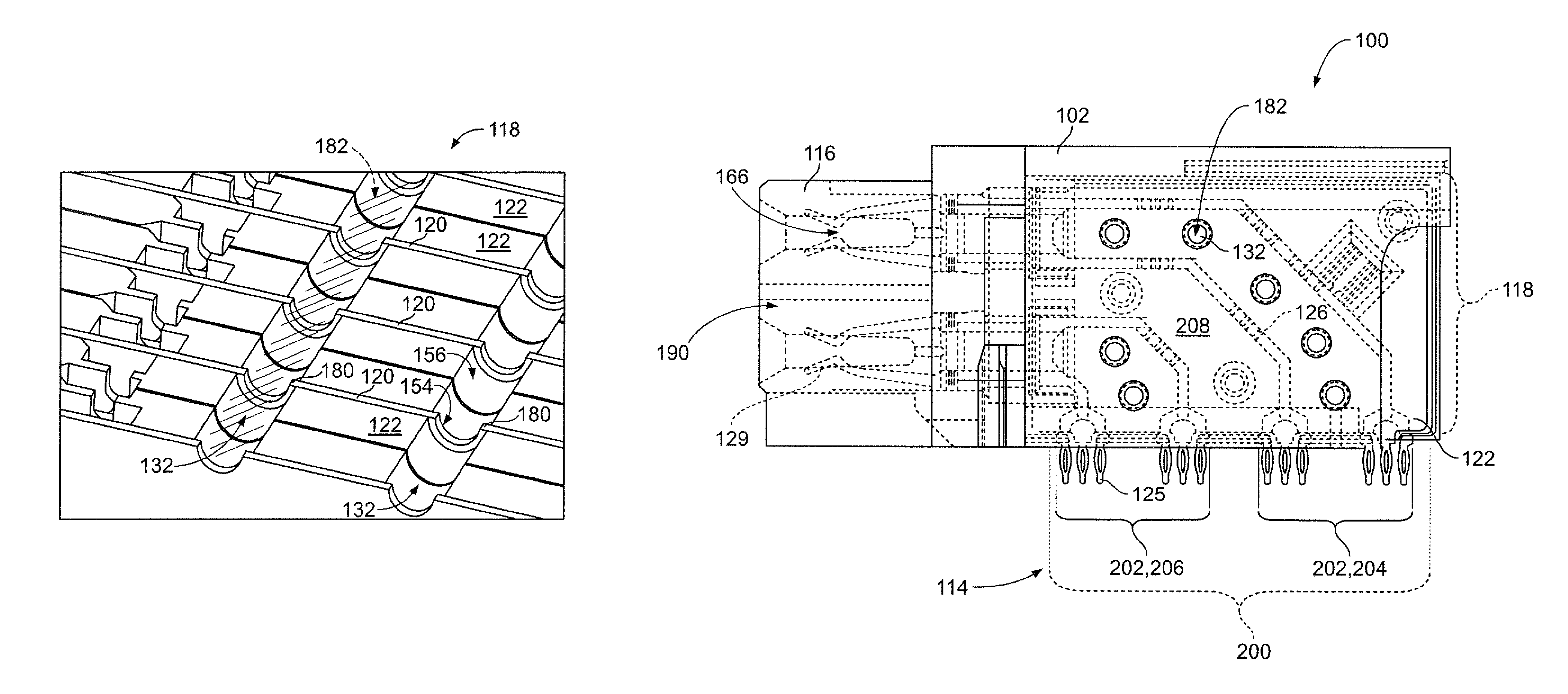
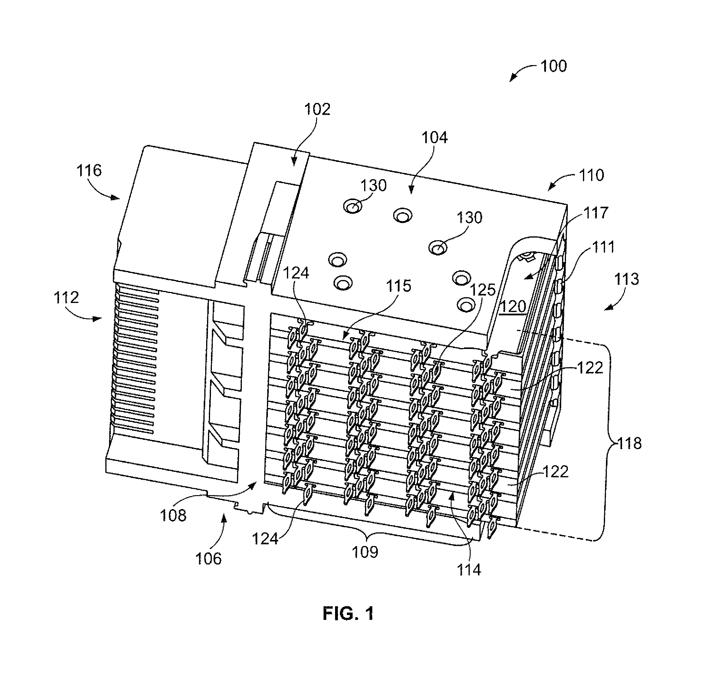
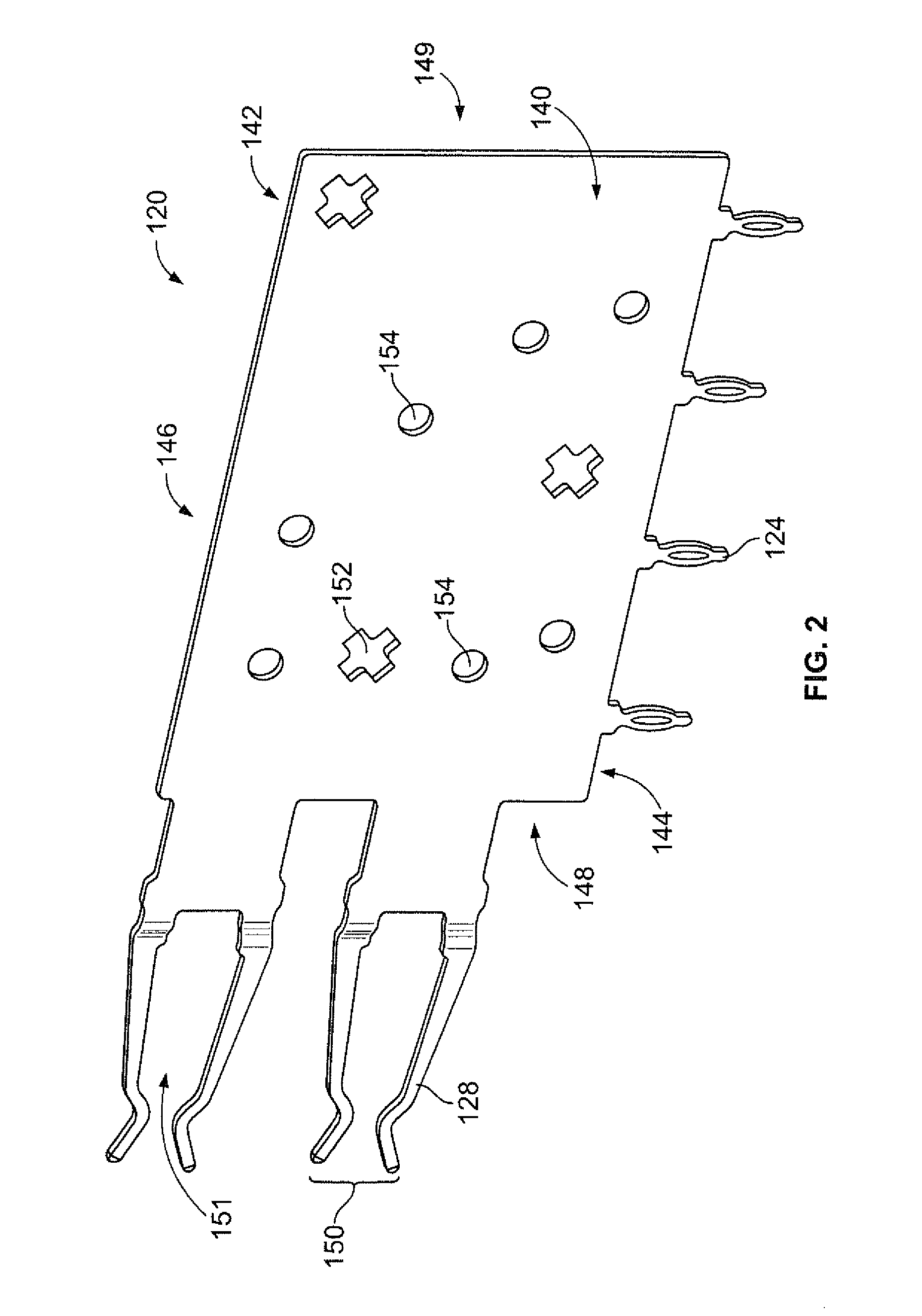
[0017]Embodiments described herein include a multiport connector having a conductive elastomeric material extending therethrough. The conductive elastomeric material conductively couples each of the ground plate...


PUM


Abstract

An electrical connector is provided having a housing. Contact modules are positioned within the housing. The contact modules each have a dielectric body holding at least one conductive lead. The at least one conductive lead extends between a mating end and a mounting end. The mating end is configured to be electrically connected to an electrical component. The mounting end is configured to be electrically connected to a circuit board. Ground plates are positioned within the housing between corresponding contact modules. The contact modules and the ground plates form a contact assembly held by the housing. A conductive elastomeric material extends through the contact modules and engages the ground plates to electrically interconnect the ground plates.

Description

BACKGROUND OF THE INVENTION[0001]The subject matter described herein relates to an electrical connector.[0002]Multiport electrical connectors generally include a plurality of contact modules and ground plates stacked within a housing. The contact modules include conductive leads held within a dielectric body. The connector is mounted to a primary circuit board and receives a secondary circuit board through a mating end. The ground plates of the connector are coupled to a ground plane within the primary circuit board. The ground plates provide electrical shielding between the leads of the contact module to reduce cross-talk between the conductive leads.[0003]However, conventional multiport connectors are not without their disadvantages. In particular, the ground plates are typically only electrically connected through the primary circuit board. Through the connector, the ground plates are electrically isolated from one another. Some known multiport connectors include a conductive pin...

Claims


Application Information

Patent Timeline
Patent Type & Authority Patents(United States)
IPC IPC(8): H01R4/66
CPCH01R4/04H01R12/724H01R13/6586
Inventor SZCZESNY, DAVID S.O'KEEFE, II, JOHN J.THOMAS, DOUGLAS M.BRIANT, ERIC DAVID
Owner TE CONNECTIVITY CORP
Why Eureka
Try Eureka