Supercharge Your Innovation With Domain-Expert AI Agents!

Blow molding machine and method for producing hollow bodies

a technology of blow molding machine and hollow body, which is applied in the field of blow molding machine and to a method for producing hollow bodies, can solve the problems of striking air consumption, large amount of air is needed, and relatively high air consumption

Inactive Publication Date: 2014-06-10
KRONES AG
View PDF14 Cites 0 Cited by
  • Summary
  • Abstract
  • Description
  • Claims
  • Application Information

AI Technical Summary

Benefits of technology

The present disclosure provides a blow molding machine and method for blow molding hollow bodies that saves blow air. The machine uses a piston to seal the hollow body and compress the blow air, which helps to increase the pressure during blowing. This saves blow air and improves the efficiency of the blow molding process.

Problems solved by technology

A relatively great amount of air is however needed for blow molding the hollow body, and the air consumption is here relatively high especially in the manufacture of wide-necked containers, such as e.g. cups or cans or the like.
With the great number of hollow bodies produced, this air consumption is striking under procedural and economic aspects.
The amount of blow air saved is however relatively small.

Method used


Image

  • Blow molding machine and method for producing hollow bodies
  • Blow molding machine and method for producing hollow bodies

Examples


Embodiment Construction

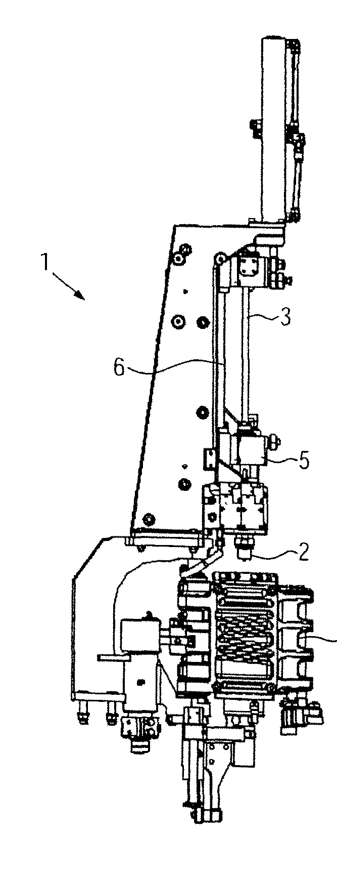
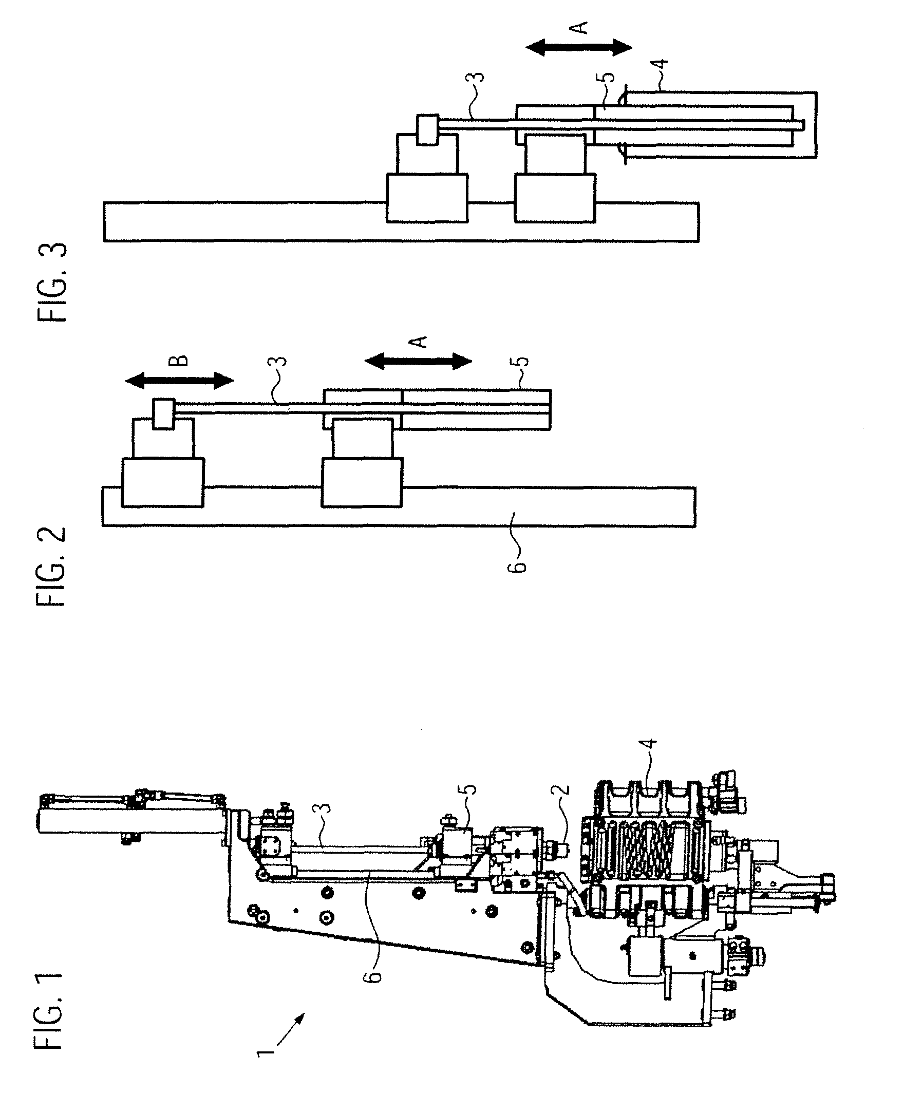
[0017]FIG. 1 shows one of the blow molding stations 1 of a blow molding machine, which is here configured as a stretch blow molding machine, i.e. it contains a stretching rod 3 apart from a blow nozzle 2. As a rule, the stretching rod 3 is coaxially arranged inside the blow nozzle 2 and is movable relative to the blow nozzle 2. A hollow mold 4 is positioned underneath the blow nozzle 2; a preform (not shown here) is inserted into the hollow mold in the customary way and is pressed by way of blowing by means of the blow nozzle 2 and by mechanical stretching with the help of the stretching mandrel 3 against the inner walls of the hollow mold 4 so as to achieve the desired shape.

[0018]The blow nozzle 2 and the stretching rod 3 are controlled in the customary way via a pneumatic cylinder and a cam.

[0019]According to the disclosure a blow plunger 5 is provided, in addition to the blow nozzle 2 and the stretching rod 3. The blow plunger 5 is arranged to be coaxial to the blow nozzle 2 and...


PUM

PropertyMeasurementUnit
outer diameteraaaaaaaaaa
diameteraaaaaaaaaa

Abstract

A blow molding machine for producing hollow bodies, particularly wide-necked containers, having a blow nozzle and a blow mold for accommodating a preform. To save air during the blowing process in a simple way, a plunger is introduced into the preform during the blowing operation.

Description

CROSS-REFERENCE TO RELATED APPLICATION[0001]The present application claims the benefit of priority of German Application No. 102009031681.7, filed Jul. 3, 2009. The entire text of the priority application is incorporated herein by reference in its entirety.FIELD OF THE DISCLOSURE[0002]The present disclosure refers to a blow molding machine and to a method for producing hollow bodies of the type used in forming containers.[0003]Such a blow molding machine is known from EP 1 328 396. The known blow molding machine includes a split blow mold into which a preform is inserted that is then pressed with the help of compressed air out of a blow nozzle against the walls of the blow mold and is thereby shaped into the hollow body. A relatively great amount of air is however needed for blow molding the hollow body, and the air consumption is here relatively high especially in the manufacture of wide-necked containers, such as e.g. cups or cans or the like. With the great number of hollow bodie...

Claims


Application Information

Patent Timeline
Patent Type & Authority Patents(United States)
IPC IPC(8): B29C43/22
CPCB29C49/58B29C49/783B29K2067/00B29C49/12B29C49/16Y02P70/10B29C49/42855B29C49/4286B29C2049/7834B29C2049/7879
Inventor VOTH, KLAUS
Owner KRONES AG
Features
  • R&D
  • Intellectual Property
  • Life Sciences
  • Materials
  • Tech Scout
  • Unparalleled Data Quality
  • Higher Quality Content
  • 60% Fewer Hallucinations
Learn More