
Image forming apparatus and image forming method

a technology of image forming apparatus and forming method, which is applied in the direction of electrographic process apparatus, corona discharge, instruments, etc., can solve the problems of significant deterioration in image quality, failure of photosensitive member charge, and failure to consider the switch of print speed, so as to achieve the effect of well maintaining the quality of the printed imag

Inactive Publication Date: 2014-06-17
MURATA MASCH LTD
View PDF12 Cites 0 Cited by
  • Summary
  • Abstract
  • Description
  • Claims
  • Application Information

AI Technical Summary

Benefits of technology

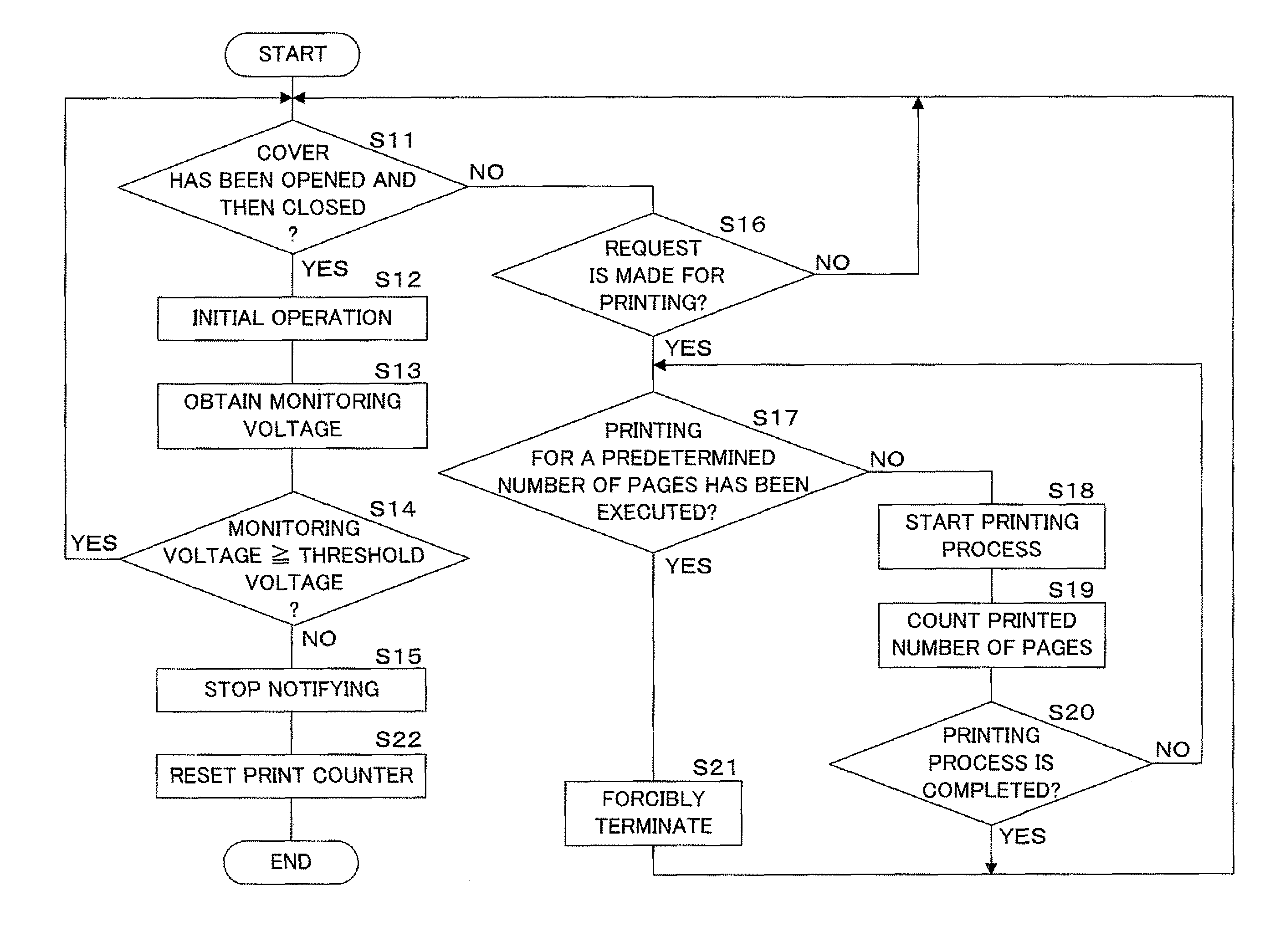
The present invention provides an image forming apparatus and an image forming method that can appropriately determine whether or not the charger needs to be cleaned depending on each print speed, even if the print speed is switched. The image forming apparatus includes a cleaning member arranged to clean a surface of the discharge member when it is determined that the discharge member needs to be cleaned. This helps to maintain the clean condition of the discharge member, which is important for avoiding charge failure and maintaining the quality of the printed image. The image forming apparatus appropriately determines the necessity to clean the discharge member of the corona discharger that charges the surface of the image bearing body, and prevents a charge failure of the image bearing body. The image forming apparatus also counts the number of printed pages when the discharge member needs to be cleaned, and prevents printing thereafter to avoid deterioration in the image quality. Overall, the image forming apparatus and method provide a better solution for keeping the printing process clean and efficient.

Problems solved by technology

It has been known that, in the charger of the corona discharging system, if dirt is adhered to the corona wire, the photosensitive member is not normally charged at the portion that contains the dirt, causing a charge failure at the photosensitive member.
Such a charge failure results in significant deterioration in image quality because, for example, a solid black area may be formed on the printed image.
The Japanese Patent Application Laid-Open No. 2006-184826, however, does not consider switching of the print speed.
Therefore, in the image forming apparatus capable of processing with two or more types of print speeds, it is difficult to determine appropriately whether or not the corona wire needs to be cleaned depending on each print speed.

Method used


Image

  • Image forming apparatus and image forming method
  • Image forming apparatus and image forming method
  • Image forming apparatus and image forming method

Examples


Embodiment Construction

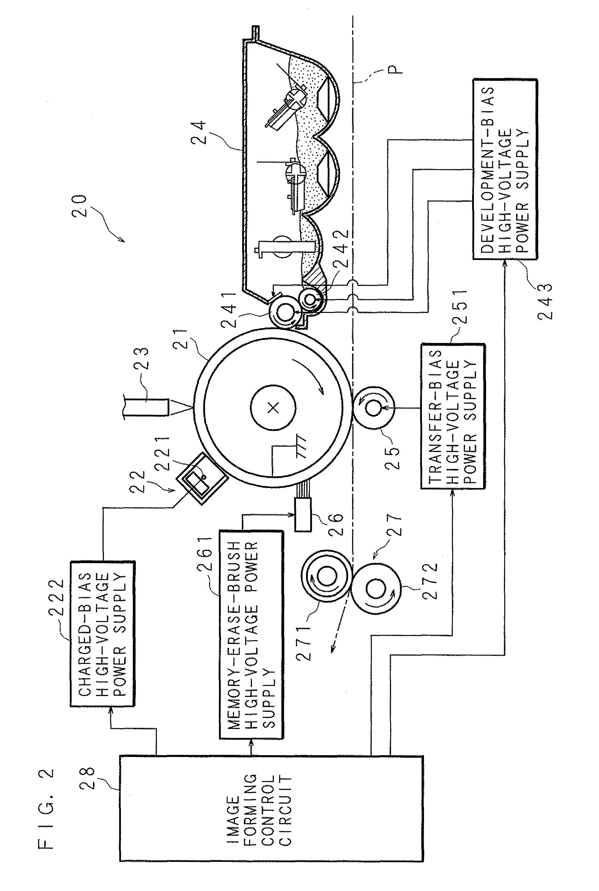
[0035]The following will describe in detail an image forming apparatus according to preferred embodiments of the present invention with reference to the drawings. In the description below, the image forming apparatus according to preferred embodiments of the present invention will be explained as, for example, including a scanner function to read an image of an original document and a print function to form an image on a paper such as a copy paper or an OHP (Over Head Projector) sheet, for example, based on image data. The image forming apparatus according to preferred embodiments of the present invention may also include, in addition to the functions described above, a communicating function to transmit / receive data to / from an external device through a network, a facsimile function to transmit or receive data to / from an external facsimile device through a modem, and the like.

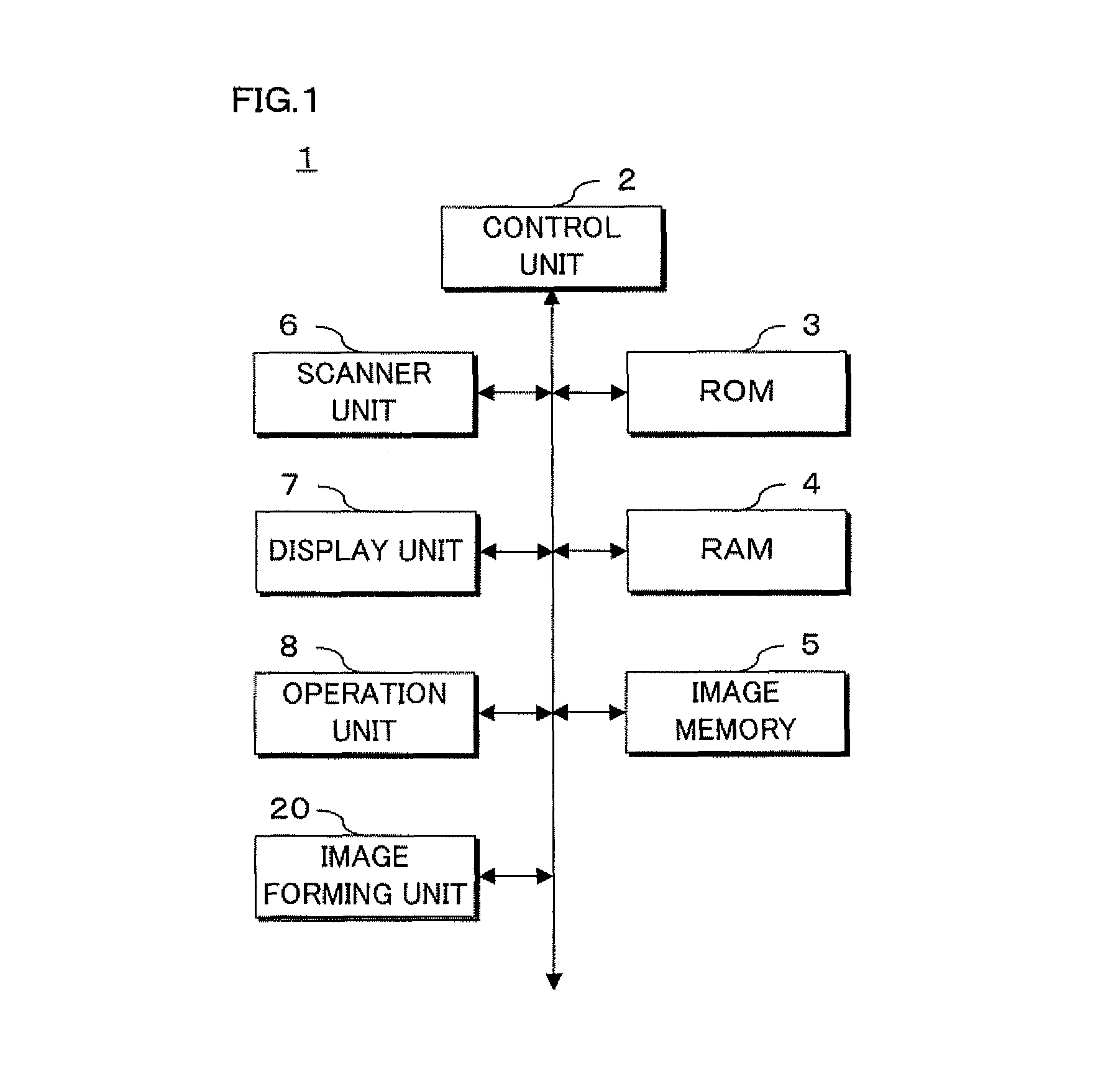
[0036]FIG. 1 is a block diagram illustrating the internal configuration of the image forming apparatus accor...


PUM


Abstract

When printing, an image forming apparatus determines, based on a threshold voltage corresponding to a print speed during printing, whether or not a corona wire of a charger needs to be cleaned. On the basis of whether or not a monitoring voltage corresponding to a current value of a charged bias, which is applied to the corona wire by a charged-bias high-voltage power supply, is equal to or more than a predetermined threshold voltage corresponding to the print speed during printing, the image forming apparatus determines whether or not the corona wire needs to be cleaned.

Description

BACKGROUND OF THE INVENTION[0001]1. Field of the Invention[0002]The present invention relates to an image forming apparatus and an image forming method using a discharger in which a corona discharging system is used, and forming an image based on image data on a paper by an electrophotographic system.[0003]2. Description of the Related Art[0004]An image forming apparatus using an electrophotographic process exposes a photosensitive member (image bearing body) charged by a charger based on image data to be processed, to form an electrostatic latent image on the photosensitive member. Moreover, the image forming apparatus supplies charged toner (developer) to the latent image by a developing unit, to form a toner image on the photosensitive member. The image forming apparatus transfers the toner image formed on the photosensitive member onto a paper by a transfer unit. The image forming apparatus then fuses the transferred toner image to the paper by a fuser, to form an image on the p...

Claims


Application Information

Patent Timeline
Patent Type & Authority Patents(United States)
IPC IPC(8): G03G15/00G03G15/02
CPCG03G15/0258G03G15/0291G03G15/0225G03G2215/027
Inventor SASAI, TAKAHIROSUZUKI, YUJITARUNO, YOSHITAKA
Owner MURATA MASCH LTD
Learn More