Systems, devices, and methods for monitoring an under foot load profile of a patient during a period of partial weight bearing

a technology for underfoot load and monitoring system, applied in medical science, diagnostics, non-surgical orthopedic devices, etc., can solve the problems of significant cost, significant time-consuming, and annual direct cost for the united states of about $1.2 billion usd

Active Publication Date: 2014-06-24
UNIV OF UTAH RES FOUND
View PDF18 Cites 6 Cited by
  • Summary
  • Abstract
  • Description
  • Claims
  • Application Information

AI Technical Summary

Problems solved by technology

Falls, sports injuries, and motor vehicle accidents are common causes of fractures.
Fractures can be very painful, can take significant time to heal, and can result in significant costs.
By some estimates, the number and severity of complications associated with tibial fractures results in an annual direct cost for the United States of about $1.2 billion USD.
When indirect costs such as lost wages are factored, in the long rehabilitation period for tibial fracture patients results in an estimated annual indirect cost of about $95 billion USD.
Unfortunately, little data has been collected to support a conclusion that PWB prescriptions are effective at either promoting fracture healing or reducing the risk of complications.

Method used


Image

  • Systems, devices, and methods for monitoring an under foot load profile of a patient during a period of partial weight bearing
  • Systems, devices, and methods for monitoring an under foot load profile of a patient during a period of partial weight bearing
  • Systems, devices, and methods for monitoring an under foot load profile of a patient during a period of partial weight bearing

Examples


working examples

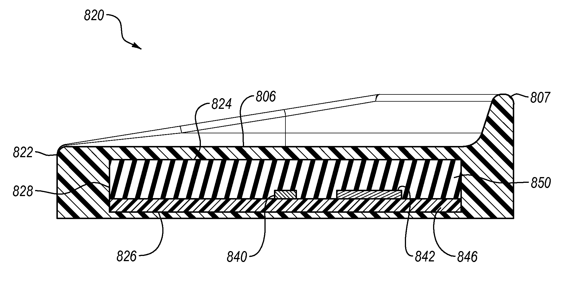
[0121]An embodiment of a load sensor was configured as a piston and cylinder design similar to that illustrated in FIG. 3A, utilizing non-compressible silicone gel to generally uniformly transmit the pressure inside the cylinder to a piezoresistive Wheatstone bridge pressure sensor. In this example, the cylinder diameter remained substantially constant and the pressure measured by the piezoresistive sensor was converted to load.

[0122]One corner of a piezoresistive pressure sensor die (a gauge-type microsensor—3000 series 15 psi piezoresistive pressure sensor manufactured by Merit Sensors, Salt Lake City, USA) was secured to a custom FR-4 printed circuit board (Circuit Graphics, Salt Lake City, USA) using UV-cure adhesive (3311 Loctite, Henkel Co., Düsseldorf, Germany). The piezoresistive sensor was electrically connected to the printed circuit board by bonding aluminum-1% silicon alloy wire (Semiconductor Packaging Materials, Inc, Armonk, USA) between the pressure sensor die and the...


PUM


Abstract

Systems, devices, and methods for measuring an under foot load profile of a patient during a period of partial weight bearing are described. The system may include a walking boot cast. A housing, including an inner surface and an upper surface that cooperate to define an inner cavity, may be oriented with respect to a patient's leg. The upper surface may be slidably received within the inner cavity in a piston and cylinder configuration or may be otherwise configured. The system may include a pressure sensor configured to monitor the load profile of a patient during the desired period of partial weight bearing. The pressure sensor may be located below the upper surface. The system may include a noncompressible force transmitter positioned within the inner cavity and at least partially encapsulating an upper portion of the pressure sensor to transmit pressure within the housing to the pressure sensor.

Description

CROSS-REFERENCE TO RELATED APPLICATIONS[0001]This application is a continuation-in-part of, and claims the benefit of and priority to, U.S. patent application Ser. No. 12 / 833,214, filed on Jul. 9, 2010, and entitled “SYSTEMS, DEVICES, AND METHODS FOR MONITORING AN UNDER FOOT LOAD PROFILE OF A TIBIAL FRACTURE PATIENT DURING A PERIOD OF PARTIAL WEIGHT BEARING”, which application is hereby expressly incorporated herein by this reference in its entirety.BACKGROUND[0002]1. The Field of the Disclosure[0003]The present disclosure relates generally to systems, devices, and methods for measuring under foot load profiles. More particularly, the disclosure relates to systems, devices, and methods for monitoring an under foot load profile of a patient during a period of partial weight bearing (PWB).[0004]2. The Relevant Technology[0005]Bone fractures, or broken bones, may be caused by direct or indirect forces to a bone, or as a result of certain medical conditions, such as osteoporosis. Falls,...

Claims


Application Information

Patent Timeline
Patent Type & Authority Patents(United States)
IPC IPC(8): A61B5/103A61F5/052
CPCA61B5/6812A61B2562/0247A61B5/45A61F5/01A61B5/4848A61B5/1036A61B5/6829A61B2562/12A61B5/4833
Inventor KUBIAK, ERIK N.NORTH, KYLEEHITCHCOCK, ROBERT W.
Owner UNIV OF UTAH RES FOUND
Why Eureka
Try Eureka