Low profile patient examination table

a patient examination table and low-profile technology, applied in the field of patient examination tables, can solve the problems of difficult and challenging design of patient examination tables so as to achieve these relatively low positions, and achieve the effect of effectively lowering the upper frame and the lower portion of the actuator

Inactive Publication Date: 2014-07-01
MARTIN MFG
View PDF32 Cites 19 Cited by
  • Summary
  • Abstract
  • Description
  • Claims
  • Application Information

AI Technical Summary

Benefits of technology

This patent describes an improved design for an examination table where there is a movable top frame that can be raised and lowered by way of lifting mechanisms connected between the two parts of the table. These mechanisms make it easy to adjust the height of the patient during different medical procedures without having to manually push or pull on the part of the table they're sitting on. In addition, these mechanisms help keep the table stable while raising and lowering its components.

Problems solved by technology

The technical problem addressed in this patent text is creating a patient examination table that can easily reached its lowest point to allow for easy access for patients while still maintaining sufficient strength and stability at those levels. This requires careful consideration of both the structure of the table and the operation of its lifting mechanism, which typically takes up significant space and remains connected to the base and upper frame.

Method used


Image

  • Low profile patient examination table
  • Low profile patient examination table
  • Low profile patient examination table

Examples


Embodiment Construction

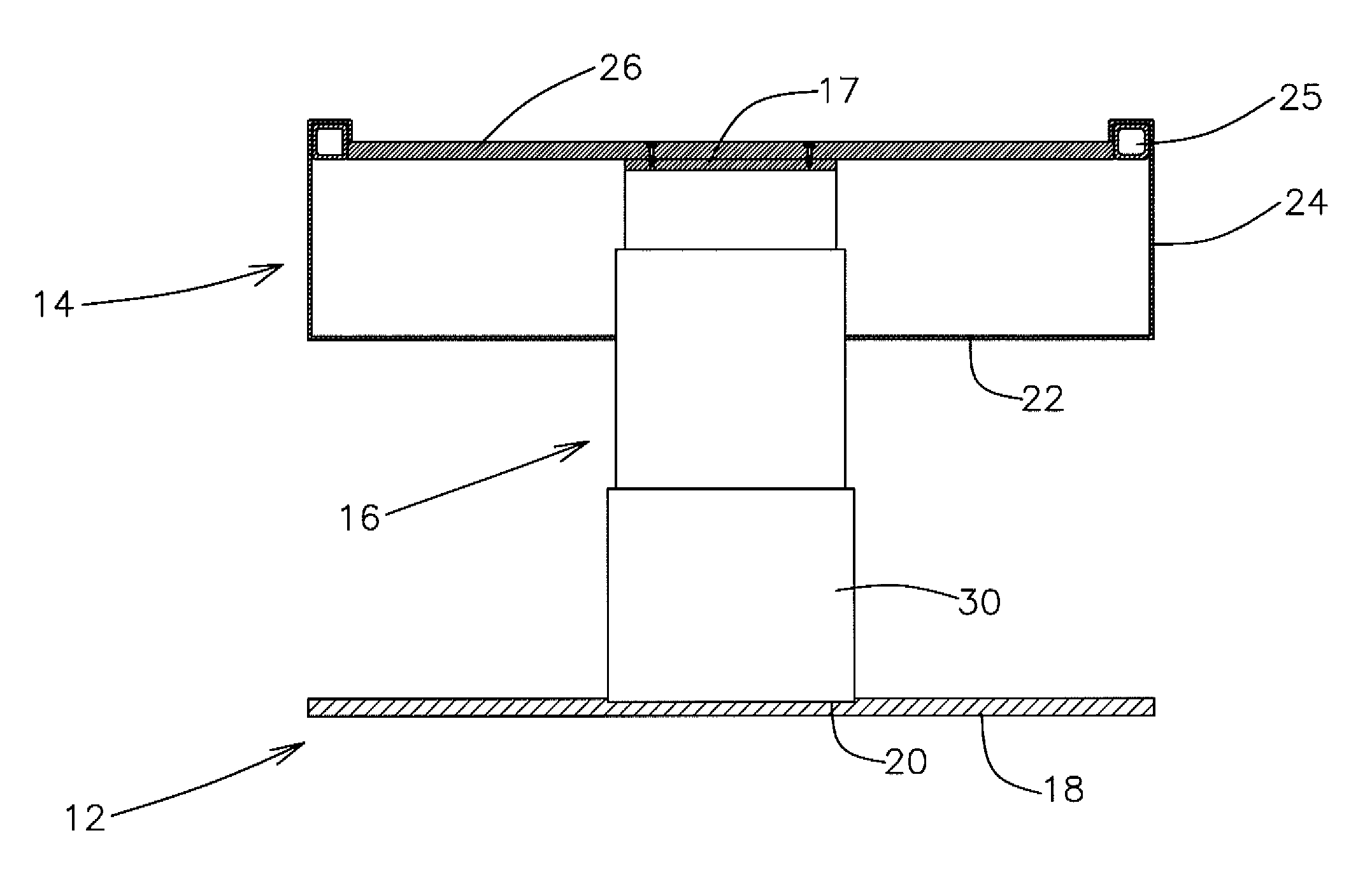
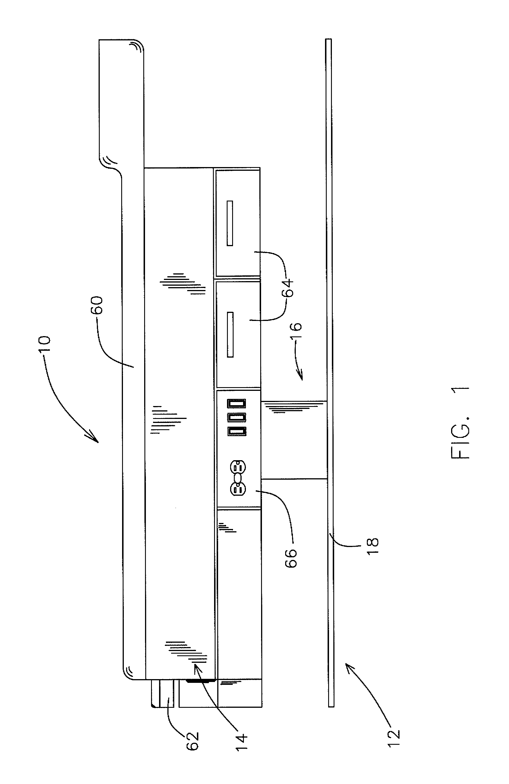
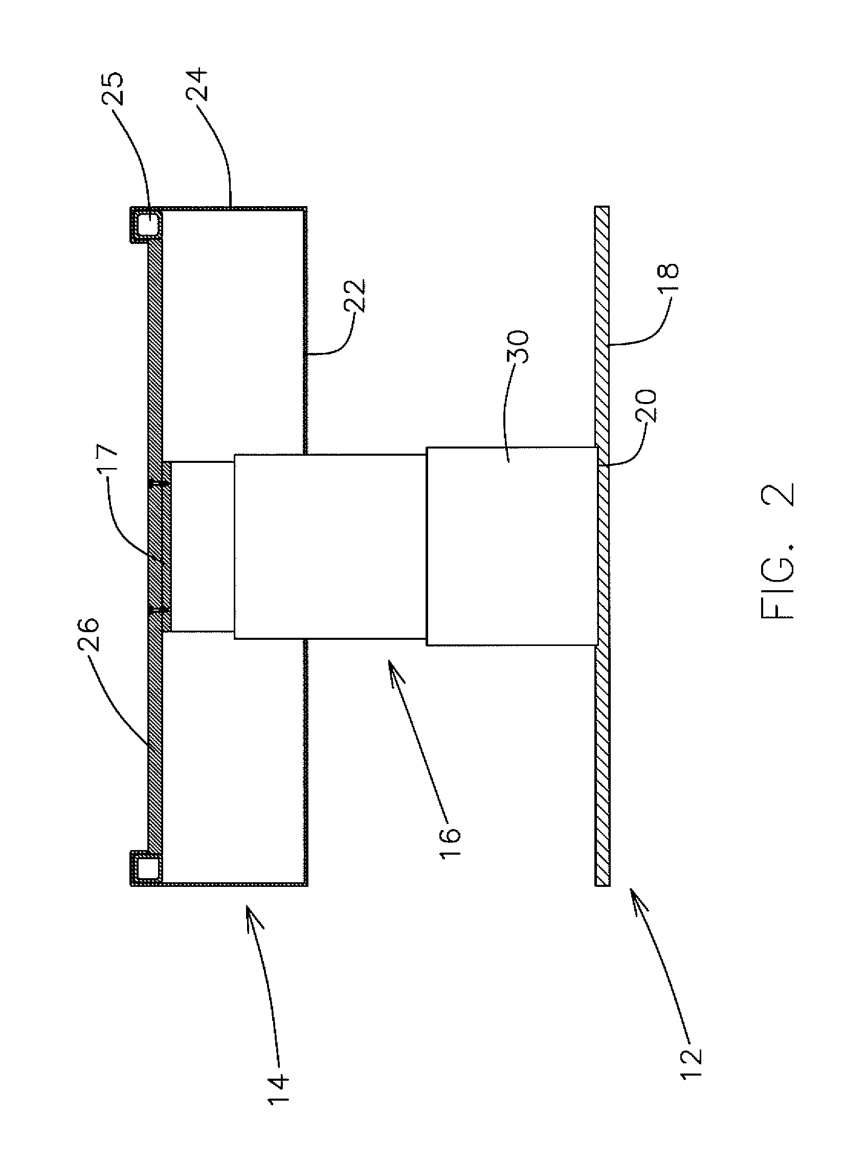
[0015]With further reference to the drawings, there is shown therein a patient examination table which is indicated generally by the number 10. As will be described subsequently herein, the patient examination table 10 is designed such that its top portion reaches a relatively low position when the examination table is fully lowered, especially with respect to commercially available patient examination tables that are available today.

[0016]FIGS. 1-4 of the drawings illustrate the three basic components of the patient examination table that enable it to be lowered to a relatively low height. These three basic components include the base of the examination table referred to generally by the number 12, an upper frame indicated generally by the number 14 and a lifting mechanism or assembly indicated generally by the number 16. While the present invention is described herein and shown in the drawings, a more complete and unified understanding of patient examination tables can be gained f...


PUM


Abstract

An examination table is shown that is capable of being lowered to a relatively low height. The examination table includes a base, a lifting mechanism, an upper frame structure, and a patient support disposed on or supported directly or indirectly by the upper frame. The lifting mechanism interconnects the base with the upper frame structure. In order to reduce the height of the examination table when it assumes the lower position, the lifting mechanism is projected upwardly through a lower portion of the upper frame such that an upper portion of the lifting mechanism assumes a position in an open area of the upper frame. Once the upper portion of the lifting mechanism is projected into the upper frame, the lifting mechanism is attached to the upper frame such that the upper frame moves up and down as the lifting mechanism moves up and down.

Description


Claims


Application Information

Patent Timeline
Owner MARTIN MFG
Why Eureka
Try Eureka