Optical engine module and projection apparatus

a technology of optical engine and projection apparatus, which is applied in the field of optical engine module and projection apparatus, can solve the problems of high overall cost and about 11% light loss, and achieve the effect of reducing costs and favorable optical effects

Active Publication Date: 2021-05-04
CORETRONIC
View PDF6 Cites 0 Cited by
  • Summary
  • Abstract
  • Description
  • Claims
  • Application Information

AI Technical Summary

Benefits of technology

[0007]The invention provides an optical engine module and a projection apparatus capable of effectively lowering the costs and providing a favorable optical effect.
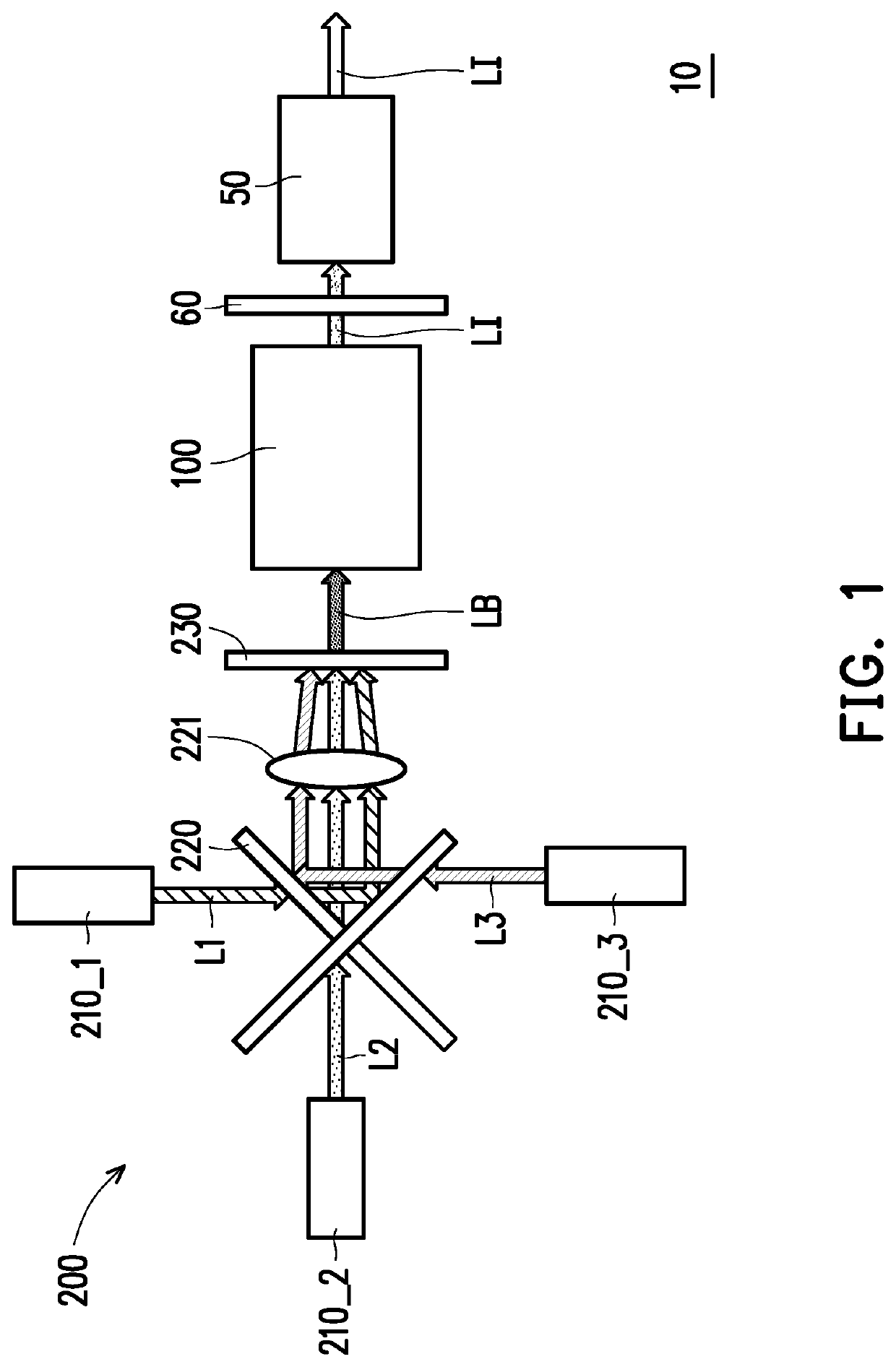
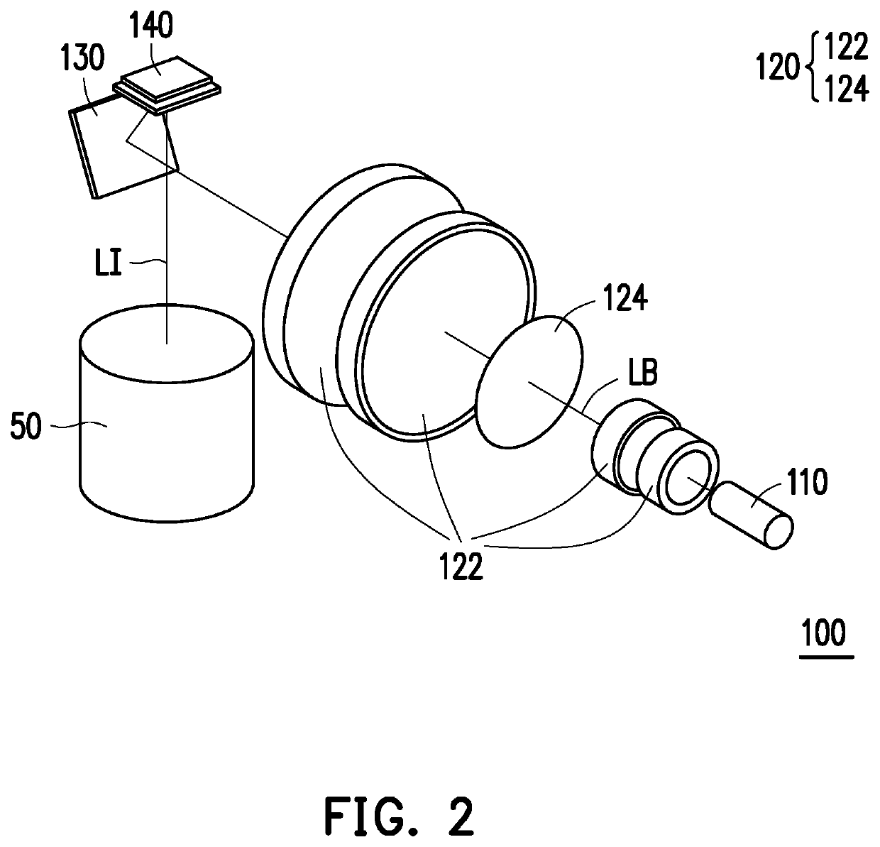
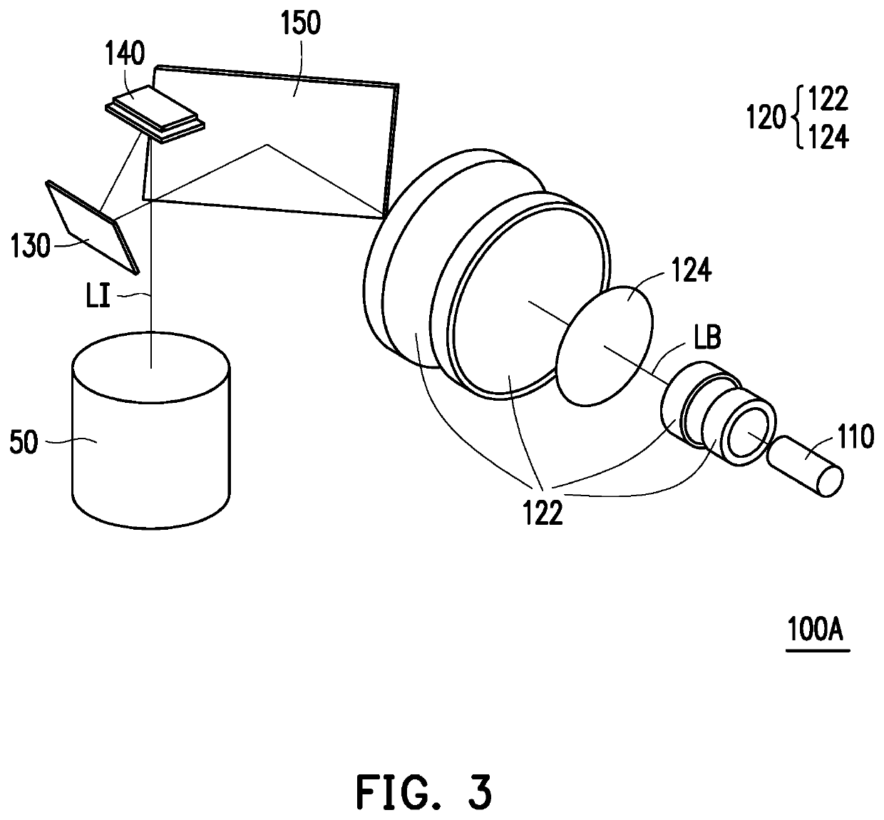
[0011]In view of the above, the embodiments of the invention have at least one of the following advantages or effects. In the projection apparatus of the invention, the optical engine module of the projection apparatus is disposed on the transmission path of the illumination beam, and this illumination beam is converted into an illumination beam with telecentric characteristics by the optical lens assembly and the reflective element of the optical engine module and is transmitted to the light valve. Therefore, the costs can be effectively reduced while a contrast ratio of the projection apparatus is enhanced, thereby providing a favorable optical effect.

Problems solved by technology

Nevertheless, the TIR prism and the R-TIR prism are relatively expensive optical elements, which will make the overall cost high; and only by applying an optical coating on an optical surface of the TIR prism / R-TIR prism that is close to the digital micromirror element and on a total reflection surface of the TIR prism / R-TIR prism, the TIR prism / R-TIR prism is able to receive light from different angles, but this optical coating will cause about 11% light loss.

Method used


Image

  • Optical engine module and projection apparatus
  • Optical engine module and projection apparatus
  • Optical engine module and projection apparatus

Examples


Embodiment Construction

[0017]In the following detailed description of the preferred embodiments, reference is made to the accompanying drawings which form a part hereof, and in which are shown by way of illustration specific embodiments in which the invention may be practiced. In this regard, directional terminology, such as “top,”“bottom,”“front,”“back,” etc., is used with reference to the orientation of the Figure(s) being described. The components of the invention can be positioned in a number of different orientations. As such, the directional terminology is used for purposes of illustration and is in no way limiting. On the other hand, the drawings are only schematic and the sizes of components may be exaggerated for clarity. It is to be understood that other embodiments may be utilized and structural changes may be made without departing from the scope of the invention. Also, it is to be understood that the phraseology and terminology used herein are for the purpose of description and should not be ...


PUM

PropertyMeasurementUnit
distanceaaaaaaaaaa
incident anglesaaaaaaaaaa
distanceaaaaaaaaaa

Abstract

An optical engine module disposed on a transmission path of an illumination beam is provided. The optical engine module includes a light homogenizing element, an optical lens assembly, a first reflective element, and a light valve. The light homogenizing element is configured to enable the illumination beam to pass through. The optical lens assembly is disposed on the transmission path of the illumination beam and constituted of at least three lenses having refractive power. The first reflective element is disposed on the transmission path of the illumination beam. The light valve is disposed on the transmission path of the illumination beam and configured to convert the illumination beam into an image beam, wherein the illumination beam is sequentially transmitted from the light homogenizing element to the optical lens assembly and the first reflective element, and is reflected to the light valve by the first reflective element.

Description

CROSS-REFERENCE TO RELATED APPLICATION[0001]This application claims the priority benefit of China application serial no. 201920612022.1, filed on Apr. 30, 2019. The entirety of the above-mentioned patent application is hereby incorporated by reference herein and made a part of this specification.BACKGROUNDTechnical Field[0002]The invention is related to an optical apparatus, and more particularly to an optical engine module and a projection apparatus.Description of Related Art[0003]A projection apparatus is a display apparatus adapted to generate a large-sized frame, and has been continuously progressing with the evolution and innovation of technology. The imaging principle of the projection apparatus is to convert an illumination beam generated by an illumination system into an image beam by a light valve (such as: a digital micromirror device), and then project the image beam through a projection lens onto a projection target (such as: a screen or a wall surface) so as to form a p...

Claims


Application Information

Patent Timeline
Patent Type & Authority Patents(United States)
IPC IPC(8): G03B21/20H04N9/31
CPCH04N9/3152G03B21/2033G03B21/2066G02B13/16G02B27/149G02B27/48G03B21/005G03B21/208H04N9/3111H04N9/3161
Inventor PAN, HAW-WOEI
Owner CORETRONIC
Why Eureka
Try Eureka