[0011]Another object is the provision of such an improved eccentric-screw pump that overcomes the above-given disadvantages, in particular that makes it possible in a manner that is cost-effective and technically simple with respect to assembly not only for changing the stator but especially also the rotor.SUMMARY OF THE INVENTION
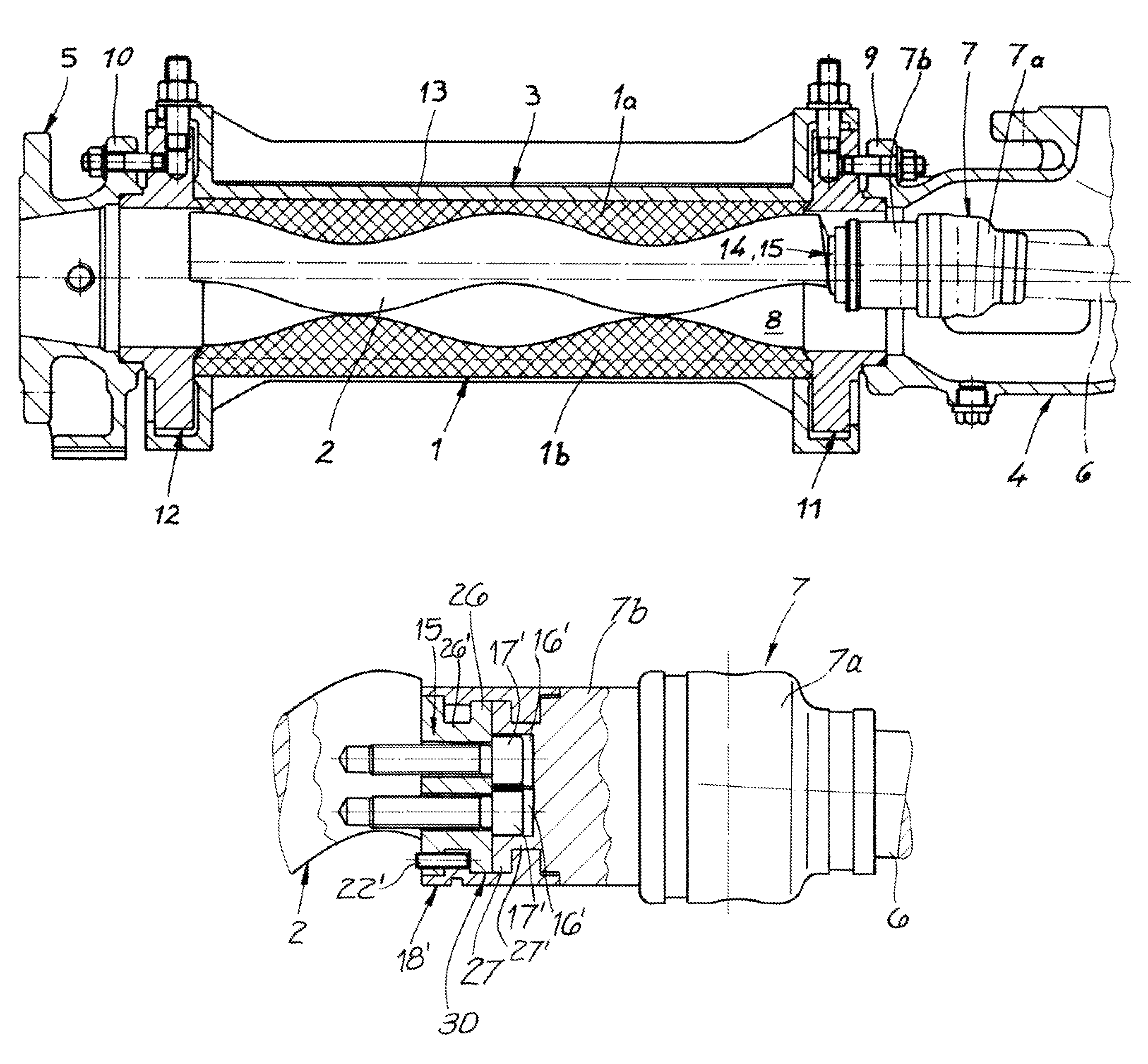
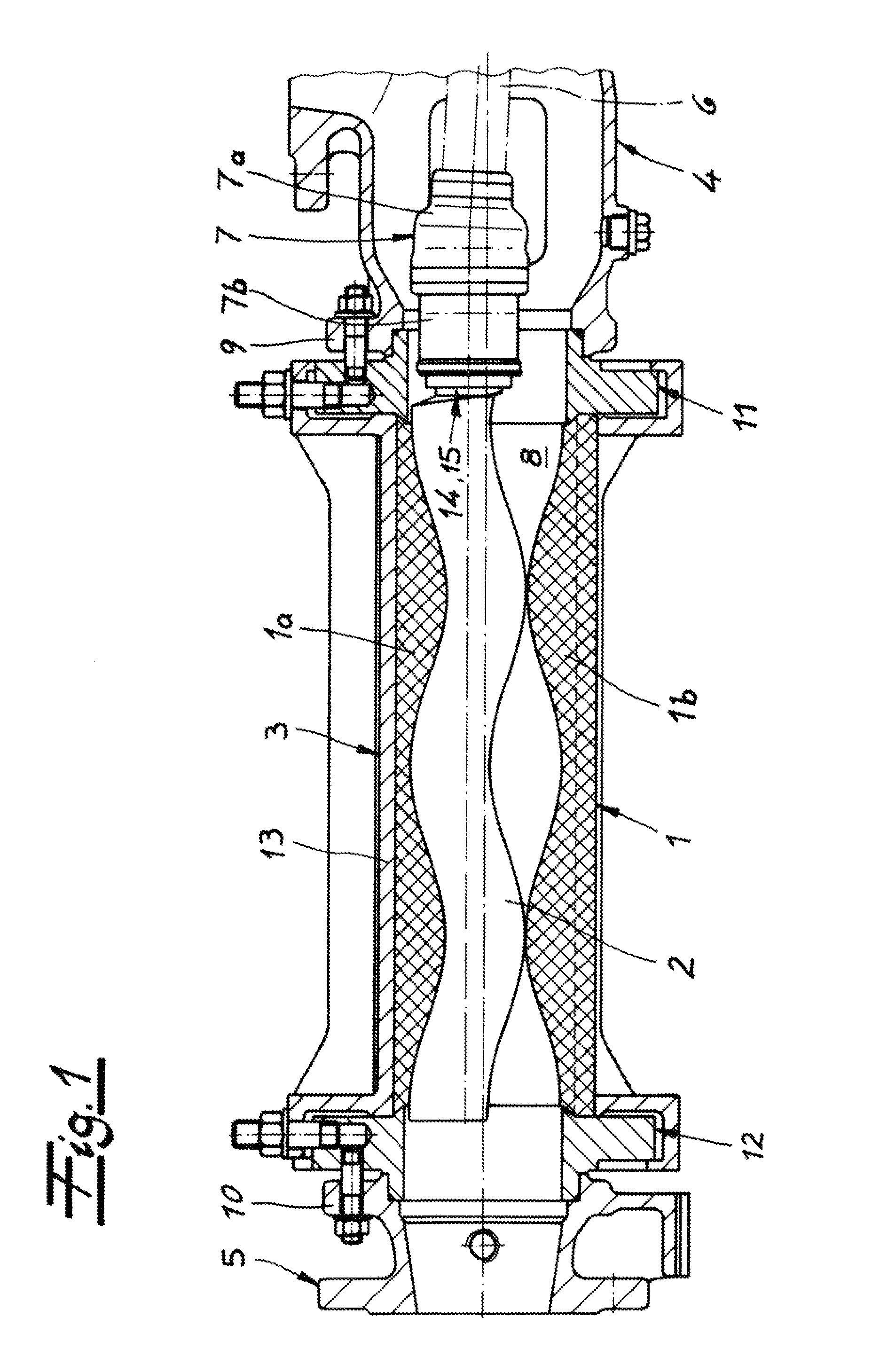
[0013]The invention initially proceeds from the recognition that the complexity of maintenance for an eccentric screw pump can be significantly reduced if the rotor of the eccentric screw pump can be exchanged in a simple manner without having to uninstall the intake or suction housing and the output or connecting housing. The invention consequently simplifies the stator exchange in an eccentric screw pump and provides more options with regard to the rotor exchange. However, for this rotor exchange it is no longer necessary to use a stator with a separate spacer ring and / or a suction housing with a removable housing segment. On the contrary, with the invention it is possible to exchange the rotor even with conventional housing arrangements. This is because, despite the limited amount of space in the area of the suction housing, in the invention a joint split is created in which the separable area may so to speak be removed axially from the suction housing. In addition, with this embodiment it is consequently not necessary to take apart the universal joint itself, but rather the joint is split between the second joint part and the rotor. However, this split or uninstalling may be accomplished without taking apart the suction housing the opening of the suction housing that faces the stator after the stator has been uninstalled. The invention thus may be realized especially in embodiments in which the stator is exchangeable without uninstalling the system. After the stator has been uninstalled, the rotor may then be uninstalled and changed, specifically without uninstalling the suction housing, since the elements to be uninstalled are all accessible axially and consequently are accessible via the open downstream end of the suction housing that is turned toward the stator.
[0014]The inventive idea is preferably used in eccentric screw pumps in which a stator exchange is done in a simple manner without uninstalling connecting housings and suction housing. The invention draws for instance on those embodiments that are known from US 2010 / 0196182. The elastically deformable stator lining is consequently provided within a rigid stator casing and may be exchanged separately therefrom. This means that the exchangeable, elastomeric stator lining is not attached to the stator casing, and especially is not glued or vulcanized thereto, but rather may be separated therefrom with nothing further for the purpose of the exchange. The stator is thus a longitudinally split stator. It comprises at least two stator parts. In a manner known per se, the stator or the parts of the stator may be attached to the connecting flange or flanges of the suction housing and / or connecting housings using one or a plurality of adapters that are bolted in both directions. Furthermore, it is advantageous when the stator casing is also a longitudinally split casing and has at least two, preferably at least three, for example four or more casing segments. With its casing segments the stator casing then forms a stator containment with which the elastomeric stator lining may be pressed radially against the rotor. The invention takes advantage of this technology, which permits simple exchange of the stator, and now additionally suggests the simple option for exchanging the rotor.
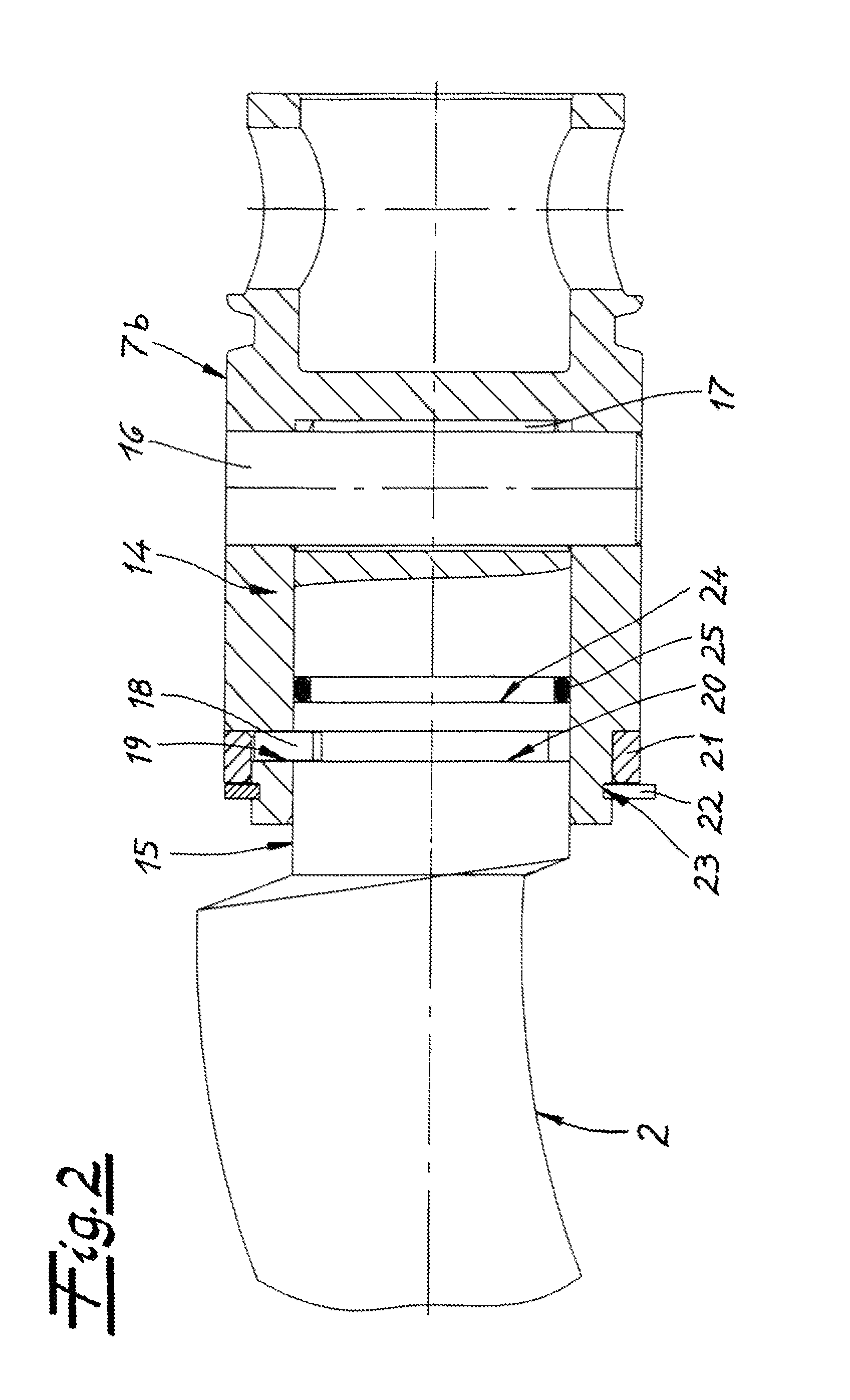
[0015]Particularly advantageous is the fact that the inventive principle is compatible with conventional eccentric screw pumps because the suction housing does not have to be modified. In particular it is not necessary to uninstall the suction housing and the suction housing also does not have to have a removable housing segment since—as explained in the foregoing—the joint split is axial, using the standard opening of the suction housing. This is because the second joint part of the universal joint inventively has a rotor socket that faces the rotor and is open on the rotor side and into which the rotor end is inserted axially, creating an angular force-transmitting connection. To this end a first coupling element is provided in the rotor socket and the rotor end has a second coupling element so that overall by inserting the rotor end into the rotor socket a coupling and thus an angular force-transmitting connection is created, the rotor end being inserted axially into the cup-shaped rotor socket and being secured axially therein. The rotor socket may also itself form the coupling element.
[0016]According to one embodiment, the coupling elements engage one another, forming a claw coupling. This may be created for instance in a simple and cost effective manner in that a diametral bolt is provided in the rotor socket as a coupling element and in that the rotor end has a fork as coupling element, the bolt during assembly engaging in the fork and creating the claw coupling. However, it is also within the invention that conversely the rotor end has the bolt and that the rotor socket has or is formed with the fork.
[0023]Overall it is within the context of the invention that there is the option of joint separation combined with axial securing. This axial securing makes it possible for the pump to be operated in both rotational directions despite the joint split.

