Eccentric-screw pump

a screw pump and eccentric technology, applied in the field of pumps, can solve problems such as the complex process of disassembly

Active Publication Date: 2012-03-15
SEEPEX GMBH
View PDF9 Cites 9 Cited by
  • Summary
  • Abstract
  • Description
  • Claims
  • Application Information

AI Technical Summary

Benefits of technology

[0023]Overall it is within the context of the invention that there is the option of joint separation combined with axial secu

Problems solved by technology

Since an eccentric screw pump is frequently integrated into a system that has

Method used


Image

  • Eccentric-screw pump
  • Eccentric-screw pump
  • Eccentric-screw pump

Examples


Embodiment Construction

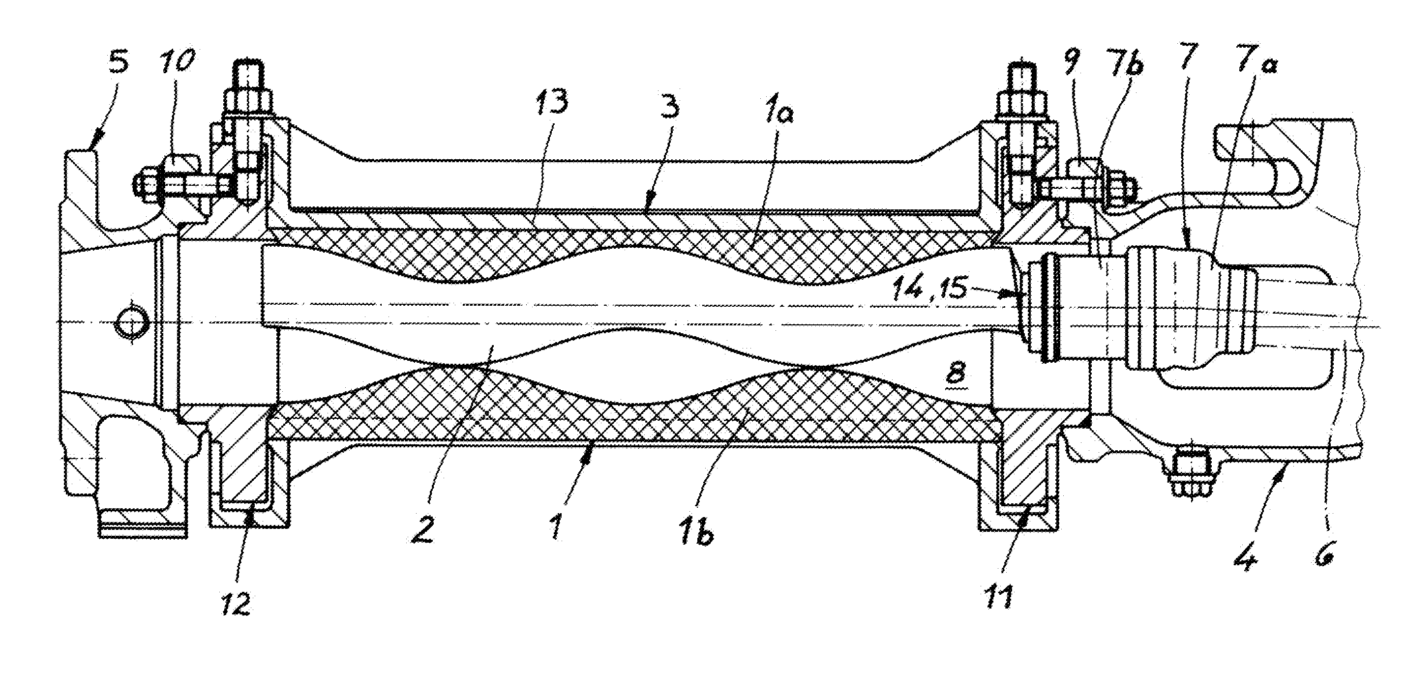
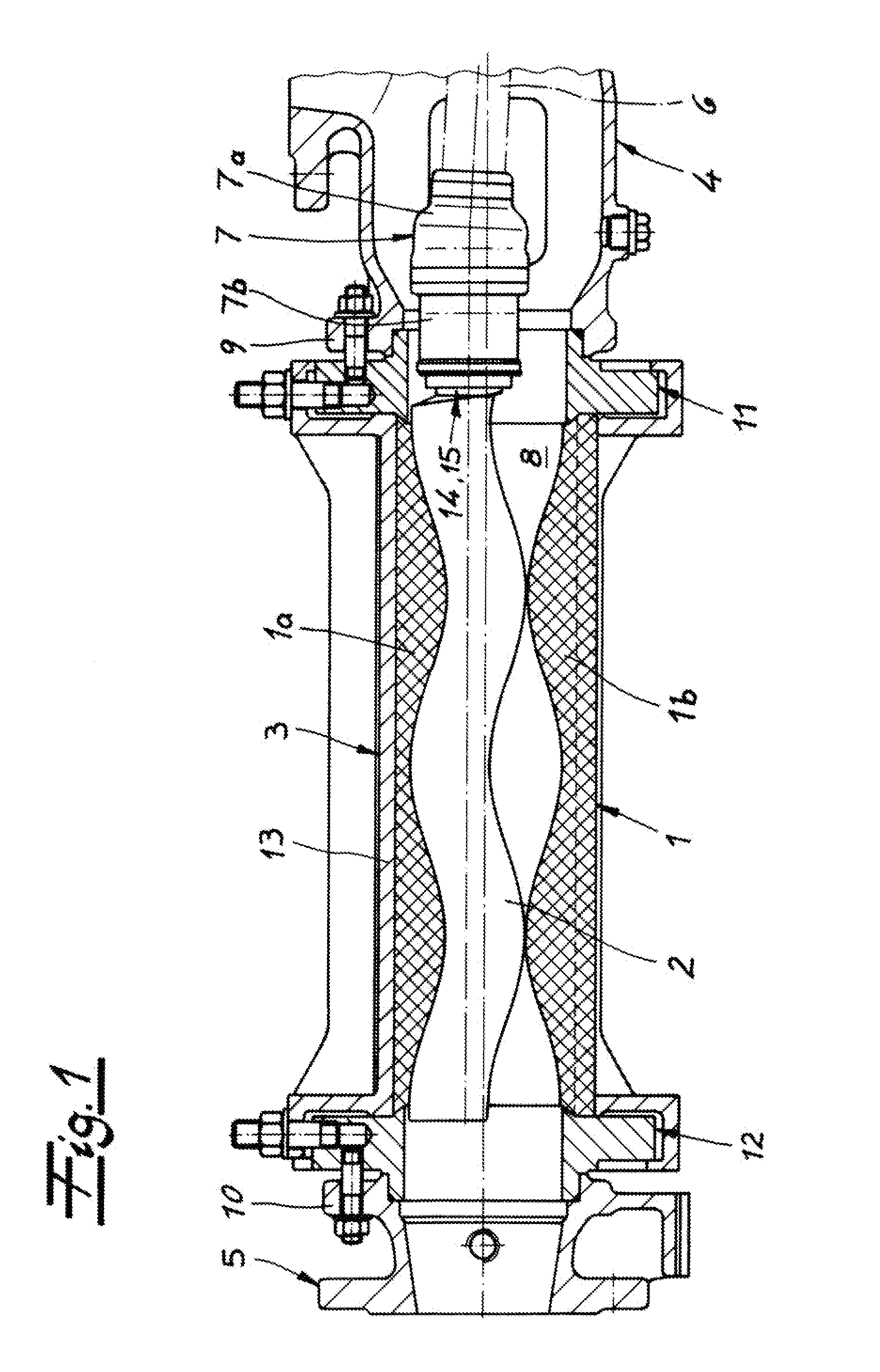
[0032]As seen in FIG. 1 an eccentric screw pump basically comprises a generally tubular stator 1 made of elastomeric material and a rotor 2 extending axially an axially throughgoing passage of an elastomeric liner forming the stator 1. The stator 1 is held in a tubular, rigid, and stationary casing 3. The stator 1 is thus elastically deformable while the stator casing 3 is rigid and made of metal. The stator 1 and casing 3 can be separated from each other.

[0033]The pump furthermore has an intake or suction housing 4 and a connecting housing 5 that is an output or pressure connector. A drive effective on the rotor 2 has a partly shown coupling rod 6 that is connected to the rotor 2 via a universal joint 7. At its opposite end it is connected via another such (unillustrated) universal coupling to an unillustrated drive motor.

[0034]The stator 1 is bolted at its one end to a connecting flange 9 of the suction housing 4 and at its other end to a connecting flange 10 of the connecting hou...


PUM


Abstract

An eccentric-screw pump has an axially split stator having axially opposite intake and output ends and an elastomeric liner defining an axially throughgoing passage. Respective intake and output housings are releasably secured to the intake and output ends of the stator. An axially extending screw rotor in the passage has an end in the intake housing. A drive includes a rotatable universal joint having a pair of relatively swivelable parts in the intake housing. Respective generally complementary formations on the end of the rotor and on one of the universal-joint parts can fit axially together to rotationally couple the one universal-joint part with the rotor. A latch secures the formations axially together for angular force transmission between the one universal-joint part and the rotor.

Description

FIELD OF THE INVENTION[0001]The present invention relates to a pump. More particularly this invention concerns an eccentric-screw pump.BACKGROUND OF THE INVENTION[0002]An eccentric screw pump typically has at least one stator and one rotor rotatable in the stator. A suction housing is provided at one end of the stator and a connector at the axially opposite other end. The rotor is attached inside the suction housing to a coupling rod or drive shaft via a universal joint having an input-side first part and a rotor-side second part swivelable relative to the first joint part. The rotor is detachably connected to the second joint part of the joint.[0003]The stator is normally made of an elastic material and is enclosed by a rigid stator casing, made for example of metal. According to the invention, the elastic material is an elastomer, for example a synthetic rubber or rubber mixture. The stator casing and elastically deformable stator are preferably separate parts.[0004]During operati...

Claims


Application Information

Patent Timeline
IPC IPC(8): F01C1/10
CPCF04C2/1073F04C14/28F04C15/0065F04C15/0073F04C2230/60Y10T403/7052F04C2240/20F16D1/02Y10T403/7069Y10T403/7062F04C2230/70F16D1/116
Inventor OVERMEIER, DIRKGRIESDORN, MARCELRYVKIN, VSEVOLOD
Owner SEEPEX GMBH
Why Eureka
Try Eureka