Transmission and method of shift control for transmission

a shift control and transmission technology, applied in the direction of instruments, mechanical equipment, gearing, etc., can solve the problems of not being appropriate, not being able to make best use of the dct's advantage, giving the driver feelings of annoyance or unpleasantness, etc., to reduce annoyance or unpleasantness

Inactive Publication Date: 2014-07-01
AISIN AI CO LTD +1
View PDF13 Cites 2 Cited by
  • Summary
  • Abstract
  • Description
  • Claims
  • Application Information

AI Technical Summary

Benefits of technology

[0009]The present invention has been developed in view of the aforementioned problematic issues. It is therefore an object of the present invention to provide a transmission and a method of shift control for transmission, transmission and method which can reduce annoyance or unpleasantness that a driver might feel by making it possible to complete pre-shifting to adequate change-speed stages upon change-speed requests.

Problems solved by technology

As a result, it might not become possible to make best use of the DCT's advantage, enabling a driver to carry out change-speed operations quickly.
For example, when a driver decelerates or accelerates a vehicle abruptly, a change-speed stage for pre-shift that the conventional DCT has determined based on a vehicular condition before the abrupt deceleration or acceleration might not be an appropriate one because of a remarkable change in the vehicular condition.
However, the conventional DCT whose change-speed stage has not been shifted to the reasonable change-speed stage might give the driver feelings of annoyance or unpleasantness.

Method used


Image

  • Transmission and method of shift control for transmission
  • Transmission and method of shift control for transmission
  • Transmission and method of shift control for transmission

Examples


embodiment no.1

Embodiment No. 1

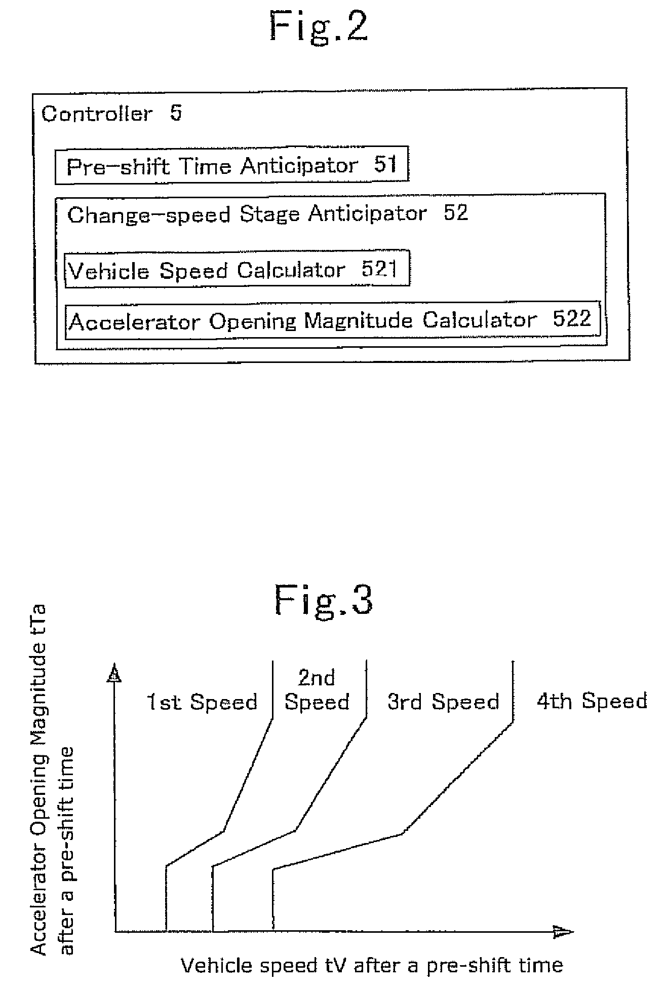
[0098]As illustrated in FIG. 2, the present transmission 1 according to Embodiment No. 1 uses the controller 5 that comprises a pre-shift time anticipator 51, a change-speed stage anticipator 52, and a not-shown change-speed controller. FIG. 2 is an explanatory diagram which depicts the controller 5 alone that is taken out of the present transmission 1. Moreover, the change-speed controller carries out change-speed control operations by means of a shift map that is shown in FIG. 3, for instance.

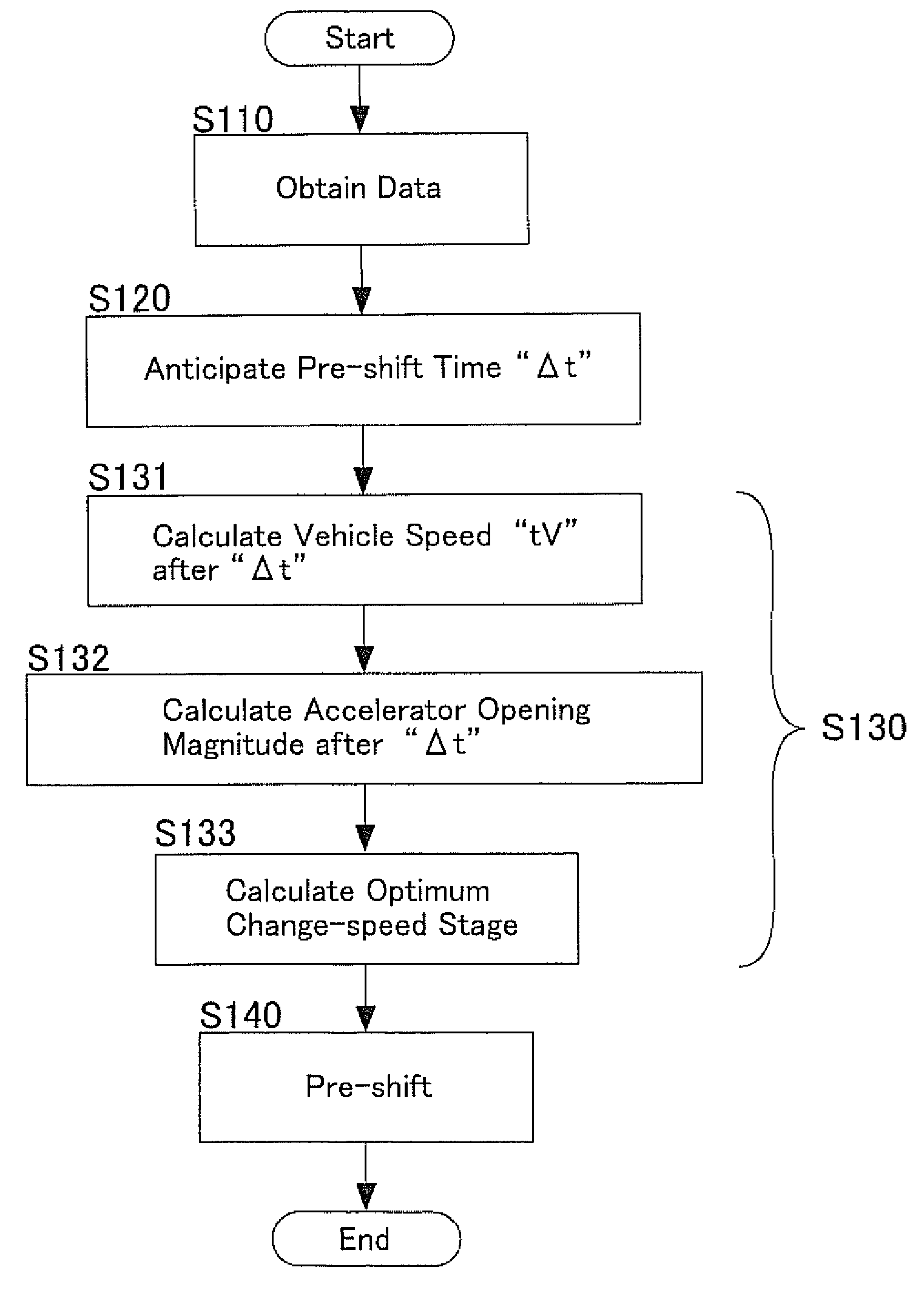
[0099]The pre-shift time anticipator 51 finds a pre-shift time “Δt” that is required when one of the first gear-mechanism selector 32 or second gear-mechanism selector 42 shifts from the current change-speed stage to a certain subsequent change-speed stage based on a state of vehicle. The term, “current change-speed stage,” refers to the following cases: one of the first gear-mechanism selector 32 or second gear-mechanism selector 42 selects one of the change-speed stages; or ...

embodiment no.2

Embodiment No. 2

[0107]As illustrated in FIG. 8, the present transmission 1 and shift-control method for transmission according to Embodiment No. 2 uses a controller 5B that comprises a pre-shift time anticipator 51, a change-speed stage anticipator 53 and a not-shown change-speed controller. FIG. 8 is an explanatory diagram for showing the controller 5B alone that is taken out of the transmission 1 according to Embodiment No. 2. In essence, the transmission 1 and shift-control method for transmission according to Embodiment No. 2 produces the same advantageous effects as those of the transmission 1 and shift-control method for transmission according to Embodiment No. 1.

[0108]For the pre-shift time anticipator 51 of the controller 5B, it is possible to employ the same pre-shift time anticipator 51 as the one used in the controller 5 that is directed to the transmission 1 according to Embodiment No. 1.

[0109]The change-speed stage anticipator 53 anticipates a subsequent change-speed st...

embodiment no.3

Embodiment No. 3

[0114]As illustrated in FIG. 11, the present transmission 1 and shift-control method for transmission according to Embodiment No. 3 uses a controller 5C that comprises a pre-shift time anticipator 51, a change-speed stage anticipator 54 and a not-shown change-speed controller. FIG. 11 is an explanatory diagram for showing the controller 5C alone that is taken out of the transmission 1 according to Embodiment No. 3. In essence, the transmission 1 and shift-control method for transmission according to Embodiment No. 3 produces the same advantageous effects as those of the transmission 1 and shift-control method for transmission according to Embodiment No. 1.

[0115]The change-speed stage anticipator 54 anticipates a subsequent change-speed stage from the change-speed stage of one of the first change-speed mechanism 3 and second change-speed mechanism 4. Note that the phrase, “one of the first change-speed mechanism 3 and second change-speed mechanism 4,” means one of the...


PUM


Abstract

A transmission includes a controller being provided with a change-speed stage anticipator. The controller adopts a time, which one of the transmission's gear-mechanism selectors requires in shifting a current change-speed stage to another change-speed stage, as a pre-shift time for selecting the latter change-speed stage. The change-speed stage anticipator operates the one of the gear-mechanism selectors while adopting a temporary change-speed stage as a subsequent change-speed stage when the temporary change-speed stage, which is estimated from a state of vehicle after the pre-shift time, the state of vehicle being relevant to each element of an anticipated change-speed stage group that is made up of one or more of the change-speed stages that can be selected by the one of the gear-mechanism selectors being set on one of the transmission's input shafts that is disconnected from a power source, coincides with an anticipated change-speed stage that corresponds to the pre-shift time.

Description

INCORPORATION BY REFERENCE[0001]The present invention is based on Japanese Patent Application No. 2009-71,979, filed on Mar. 24, 2009, the entire contents of which are incorporated herein by reference.BACKGROUND OF THE INVENTION[0002]1. Field of the Invention[0003]The present invention relates to a transmission, and a method of shift control for transmission. In particular, it relates to a dual-clutch transmission comprising two clutches, and a method of shift control for such dual-clutch transmission.[0004]2. Description of the Related Art[0005]One of transmissions for automobile is a dual-clutch transmission that comprises two clutches, namely, which uses a so-called dual-clutch mechanism, (hereinafter abbreviated to as “DCT”). Upon switching change-speed stages, the DCT is characterized in that it can carry out shifting operations quickly without cutting off or interrupting torque transmissions.[0006]As disclosed in United State Patent Application Publication No. 2007 / 0142171 A1,...

Claims


Application Information

Patent Timeline
Patent Type & Authority Patents(United States)
IPC IPC(8): G06F7/00
CPCY10T74/19219Y10T74/19251Y10T74/19288Y10T477/688Y10T74/19233F16H61/0213F16H61/688F16H2306/18Y10T477/78Y10T74/19228Y10T477/26
Inventor HATORI, HIROKITOYODA, HIROSHIMIYAZAKI, TAKESHIGEITO, YOSHIKINAGAMI, KIYOSHITAKEUCHI, ATSUSHI
Owner AISIN AI CO LTD
Why Eureka
Try Eureka