Coin and bill dispensing safe

a safe and coin-based technology, applied in the direction of coin-freed apparatus, coin dispensers, instruments, etc., can solve the problems of low efficiency of coin dispensing personnel, and inability to ensure the proper loading of dispensers, so as to minimize the inventory of money being stored, optimize the amount of money, and save costs

Active Publication Date: 2014-07-08
ELLENBY TECH
View PDF11 Cites 19 Cited by
  • Summary
  • Abstract
  • Description
  • Claims
  • Application Information

AI Technical Summary

Benefits of technology

[0012]Among its several aspects, the present invention recognizes the many failings of approaches such as those described above, and recognizes a need in the industry for a cost effective, space efficient cash accepting and dispensing safe that is secure and capable of reporting the value of the money within. There is also a need for cash accepting and dispensing safes that can be flexibly configured to adjust the number and value of coins and bills to be housed in the safe to optimize the amount of money needed to meet the needs at each location while minimizing the inventory of money being stored.
[0013]Consequently, an objective of one aspect of the current invention is to provide a rolled coin and bill dispensing safe that allows for cash acceptance providing a closed loop pay for change system.
[0014]One objective of another aspect of the current invention is to provide a rolled coin dispensing safe system that can determine the value of coins in the safe.

Problems solved by technology

Typically, there is nothing to insure the dispensers are properly loaded other than the reliability of such personnel.
The typical products currently available suffer from a number of deficiencies limiting their usefulness.
In particular, these products suffer from high cost.
They have limited flexibility to adapt to the amounts of coins and bills optimally required for a given site, or the ability to adapt to substantially different seasonal requirements, and have high service requirements.
This results in a very large and heavy product with limited capacity.
Thus, the dispensing mechanism is substantially limited in the quantity of rolls of coins or bills it can hold as it requires the front face of the secure box to be large enough to hold all the desired columns of tubes.
This approach results in a significant security issue as the person loading the machine can count incorrectly, as a result of human error, or purposely misrepresent the number of tubes in the dispenser.
Thus, an accurate accounting of the money in the secure housing is not possible.
Additionally, there is no verification of the tubes being dispensed which further leads to frustration by the user and possible disputes between end users, store owners and parties loading the dispensers.
Thus, the security of the system is subject to needless compromise.
The amount of bills put in the tubes is also a subject of potential security issues as well, as someone has to manually count and stuff the tubes.
This allows the electronics to know how many tubes are in the unit, but does not know that the correct tube or even a filled tube is being used.
This technology suffers from the ease with which the tube count can be fooled, and hence the value of the money in the unit derived therefrom.
It also suffers from many of the other issues described above relative to the potential inaccuracies of the approaches of the Meeker patents.
This technology has a number of limitations including high cost, an assumed value by counting the space needed to house a number of rolls leaving the value of each roll suspect, and a very large secure box to house the dispensers.
Additionally, there is little flexibility with respect to stocking the number of rolls of coins needed per location.
These approaches suffer from high cost, large unit size, knowledge of what was dispensed, but not what remains in the machine, and limited flexibility to control the number of rolls of coins needed in a given location.

Method used


Image

  • Coin and bill dispensing safe
  • Coin and bill dispensing safe
  • Coin and bill dispensing safe

Examples


Embodiment Construction

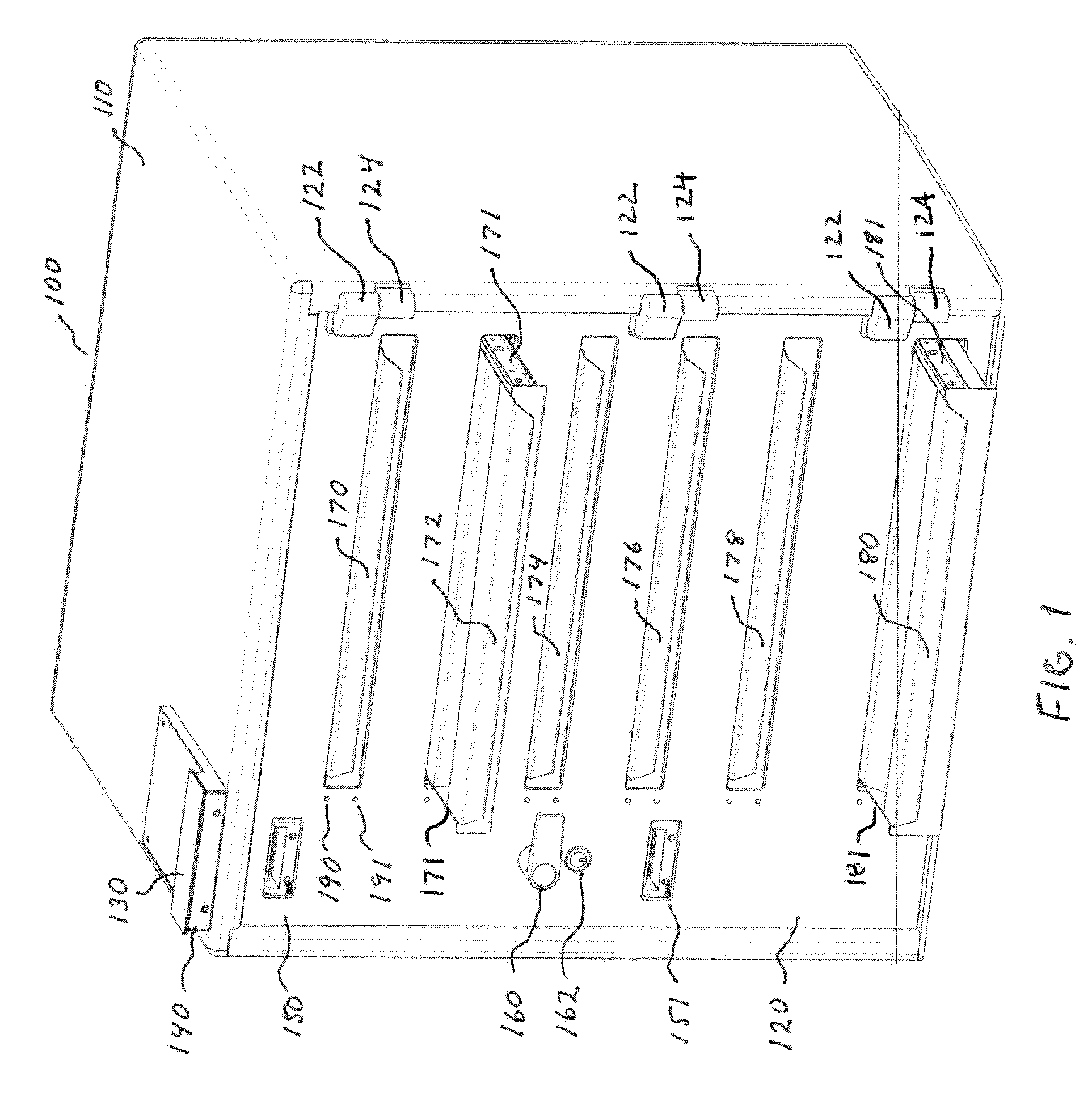
[0067]FIG. 1 shows an electronic coin and bill dispensing safe 100 including the safe housing 110 and safe door 120. In one configuration of safe 100, the safe housing 110 is made of approximately ¼ inch steel and the safe door 120 is made of ½ inch steel. The safe is preferably a Class B safe. Of course, other materials and gauges can be used as desired or required for a particular context or environment of use.

[0068]A user interface is provided through a keypad and display module 140 contained in user interface assembly 130. The material used for the assembly housing is also steel but of a much lighter gauge as a breach of the interface assembly does not allow access to the contents of the electronic safe 100. The keypad and display can both be of any suitably robust type. In a presently preferred embodiment, the keypad is a combination of a membrane overlay with conductive pads attached to a printed circuit board with conductive traces such that a depression of the membrane overl...


PUM


Abstract

A readily reconfigureable cash dispensing system for providing change, such as coins of different values and bills or currency of different denominations needed by a retail store, grocery store, busy convenience store, or the like. A tray or trays for storing and delivering multiple rolls of coins or bills of a first value, as well as, a tray or trays for storing and delivering stacks of bills are described herein. A bill acceptor may be employed to accept bills used to purchase rolls of coins and stacks of bills, and a system controller can sense restocking and dispensing events to maintain an accurate inventory of cash in the bill acceptor, as well as, the total cash stored in the form of coin rolls or rolls bills, as well as, bill stacks.

Description

[0001]This application claims the benefit of U.S. Provisional Patent Application Ser. No. 61 / 594,445 entitled “Coin and Bill Dispensing Safe” filed Feb. 3, 2012 which is hereby incorporated by reference in its entirety.FIELD OF INVENTION[0002]The current invention relates generally to the tracking and dispensing of quantities of money for change, such as rolls of coins, stacks of bills, or bills rolled up in cylinders or dispensed in tubes. More particularly, a cash dispensing unit is described which can be used in combination with one or more cash acceptors to advantageously provide a closed loop money accounting system.BACKGROUND[0003]There are a number of products on the market which will dispense rolls of coins or quantities of bills under direct or remote control. These products may contain bill or coin acceptors and may dispense the coins or bills in response to coins and bills being accepted as a way of providing change for supporting a retail or similar operation. In respons...

Claims


Application Information

Patent Timeline
Patent Type & Authority Patents(United States)
IPC IPC(8): G07D1/00G07F9/10
CPCG07D1/00G07D11/00G07D11/0087G07F9/10G07D1/02G07D7/00G07D11/10G07D11/30G07D11/32
Inventor DOBBINS, BOB M.REGER, PHILIP RENEBARNES, SCOTTCARULLO, THOMAS
Owner ELLENBY TECH
Why Eureka
Try Eureka