Circuit breaker with arc extinguishing mechanism

a circuit breaker and arc extinguishing technology, applied in the direction of circuit-breaking switch details, circuit-breaking switch operating/release mechanisms, high-tension/heavy-dress switches, etc., can solve the problems of aggravate damage on the broken component or portion, difficulty in cutting off, and large fault current flow over the system, so as to improve the efficiency of arc extinguishing

Active Publication Date: 2014-07-08
LSIS CO LTD
View PDF19 Cites 6 Cited by
  • Summary
  • Abstract
  • Description
  • Claims
  • Application Information

AI Technical Summary

Benefits of technology

[0013]Therefore, to address the drawbacks of the related art, an aspect of the detailed description is to provide an arc extinguishing mechanism for a circuit breaker capable of uniformly distributing arc, generated upon breaking a fault current, into grids so as to improve arc extinguishing efficiency.
[0015]In accordance with the aspect, the interval between the pair of insulating plates can be shorter than a width of the mover, namely, end portions of the insulating plates can protrude into the space, so as to allow the generated arc to be more smoothly introduced into the grids and simultaneously increase an amount of arc extinguishing gas generated by the insulating plates, thereby improving an arc extinguishing performance.
[0019]In accordance with the aspects of the present disclosure with the configuration, arc generated during a breaking operation can be introduced more into grids and a contact area between the arc and the insulating plates can be increased, resulting in enhancement of arc extinguishing efficiency.

Problems solved by technology

The fault current is drastically larger than the rated current, so it is difficult to be cut off.
Also, when a breakdown such as short-circuit or grounding is caused in the system, an extremely large fault current flows over the system.
If the system is left in that state, it may aggravate damage on the broken component or portion and the other may also be out of order due to large current.
Hence, it is impossible to expect an increase in the arc voltage in response to an increase in pressure.

Method used


Image

  • Circuit breaker with arc extinguishing mechanism
  • Circuit breaker with arc extinguishing mechanism
  • Circuit breaker with arc extinguishing mechanism

Examples


Embodiment Construction

[0030]Description will now be given in detail of a circuit breaker in accordance with the exemplary embodiments, with reference to the accompanying drawings. For the sake of brief description with reference to the drawings, the same or equivalent components will be provided with the same reference numbers, and description thereof will not be repeated.

[0031]FIG. 5 is a perspective view showing one exemplary embodiment of a circuit breaker in accordance with this specification, FIG. 6 is a sectional view of the one exemplary embodiment shown in FIG. 5, and FIG. 7 is a planar view of the one exemplary embodiment shown in FIG. 5.

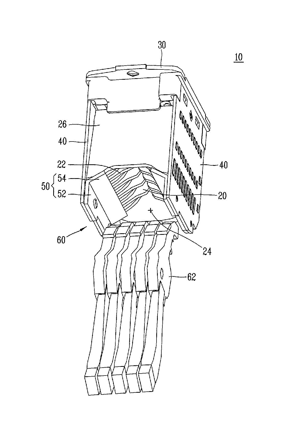
[0032]Referring to FIGS. 5 to 7, a circuit breaker 10 in accordance with the exemplary embodiment may include plural sheets of grids 20 laminated in a longitudinal (vertical) direction with predetermined intervals.

[0033]The grid 20 may be made of a metal having ferromagnetism. Protruding portion 22 may be formed at both ends at the front of each grid 20 based on...


PUM


Abstract

A circuit breaker having an arc extinguishing mechanism includes a plurality of grids disposed in a longitudinal direction, each having protruding portions at both ends thereof so as to define a space therebetween, a fixing portion to support the grids, insulating plates fixed to both sides of the grids, a stator located below the grids, the stator including an arc runner and a stationary contact disposed at an upper side of the arc runner, and a mover contactable with or separated from the stationary contact with moving up and down within the space, wherein an interval between the insulating plates within the space is shorter than a width of the mover.

Description

CROSS-REFERENCE TO RELATED APPLICATION[0001]Pursuant to 35 U.S.C. §119(a), this application claims the benefit of earlier filing date and right of priority to Korean Patent Application No. 20-2011-0001489, filed on Feb. 22, 2011, the contents of which are hereby incorporated by reference in its entirety.BACKGROUND OF THE INVENTION[0002]1. Field of the Invention[0003]This specification relates to a circuit breaker with an arc extinguishing mechanism, and particularly, to a circuit breaker with an arc extinguishing mechanism for extinguishing arc generated when a movable contactor is separated from a stationary contactor due to a fault current.[0004]2. Background of the Invention[0005]A circuit breaker is an electric device for protecting a circuit and a line by automatically breaking such circuit or line upon occurrences of an electric overload state or a short-circuit state. In general, current flowing over an electric circuit is generally divided into a rated current and a fault cu...

Claims


Application Information

Patent Timeline
Patent Type & Authority Patents(United States)
IPC IPC(8): H01H9/40
CPCH01H9/346H01H9/40H01H9/46H01H73/18H01H71/38
Inventor AN, YOUNG, GYU
Owner LSIS CO LTD
Why Eureka
Try Eureka