Night vision system

a night vision and system technology, applied in the field of night vision systems, can solve the problems of inability to use the combined scope and camera as a hands-free system, the scope or camera cannot be used in an environment where mobility is not feasible, and the weight of the sleeves coupling the night vision scope to the camera cannot be adequately supported

Active Publication Date: 2014-07-08
DEVCAR
View PDF29 Cites 9 Cited by
  • Summary
  • Abstract
  • Description
  • Claims
  • Application Information

AI Technical Summary

Benefits of technology

[0014]It is an object of the invention to teach a lightweight, night vision system that can be mounted on a user and easily deployed. In one instance, the lightweight, night vision system includes an image enhancer arranged in a casing that includes lobes which act as stabilizers when remotely deployed. An image transmission device is arranged in substantial proximity to the image enhancer. An image detection chip is arranged in proximity to the image transmission device to convert a detected image into a digital signal representative thereof. A digital signal transmitter connects to the image detection chip and transmits the digital signals to a storage medium.

Problems solved by technology

There are several disadvantages realized when performing mobile surveillance with the combined devices.
Moreover, the sleeve coupling the night vision scope to the camera cannot adequately support the weight of the scope or camera.
Thus, the combined scope and camera are not for use as a hands free system.
If the scope and camera are mounted on a tripod or other fixed structure, they are rendered immobile and cannot be used in an environment where mobility is necessary.
Thus, one cannot carry the camera with a night vision scope coupled thereto and operate it in a “hands free” manner.

Method used


Image

  • Night vision system
  • Night vision system
  • Night vision system

Examples


Embodiment Construction

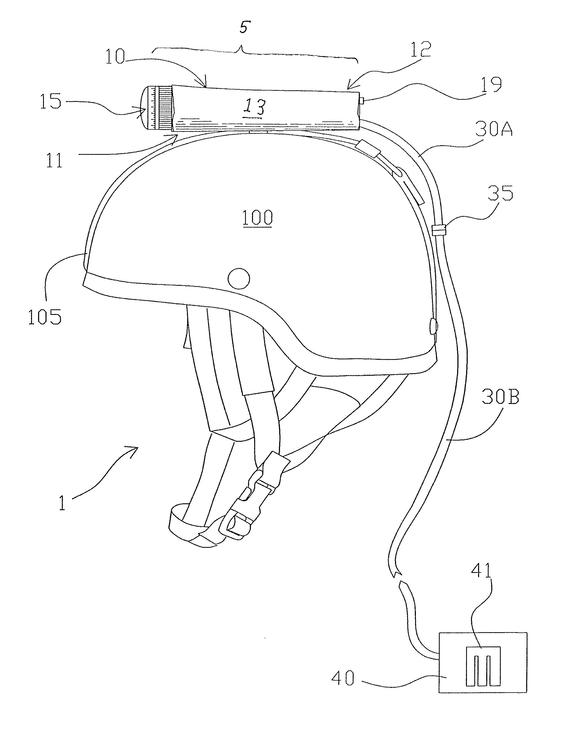
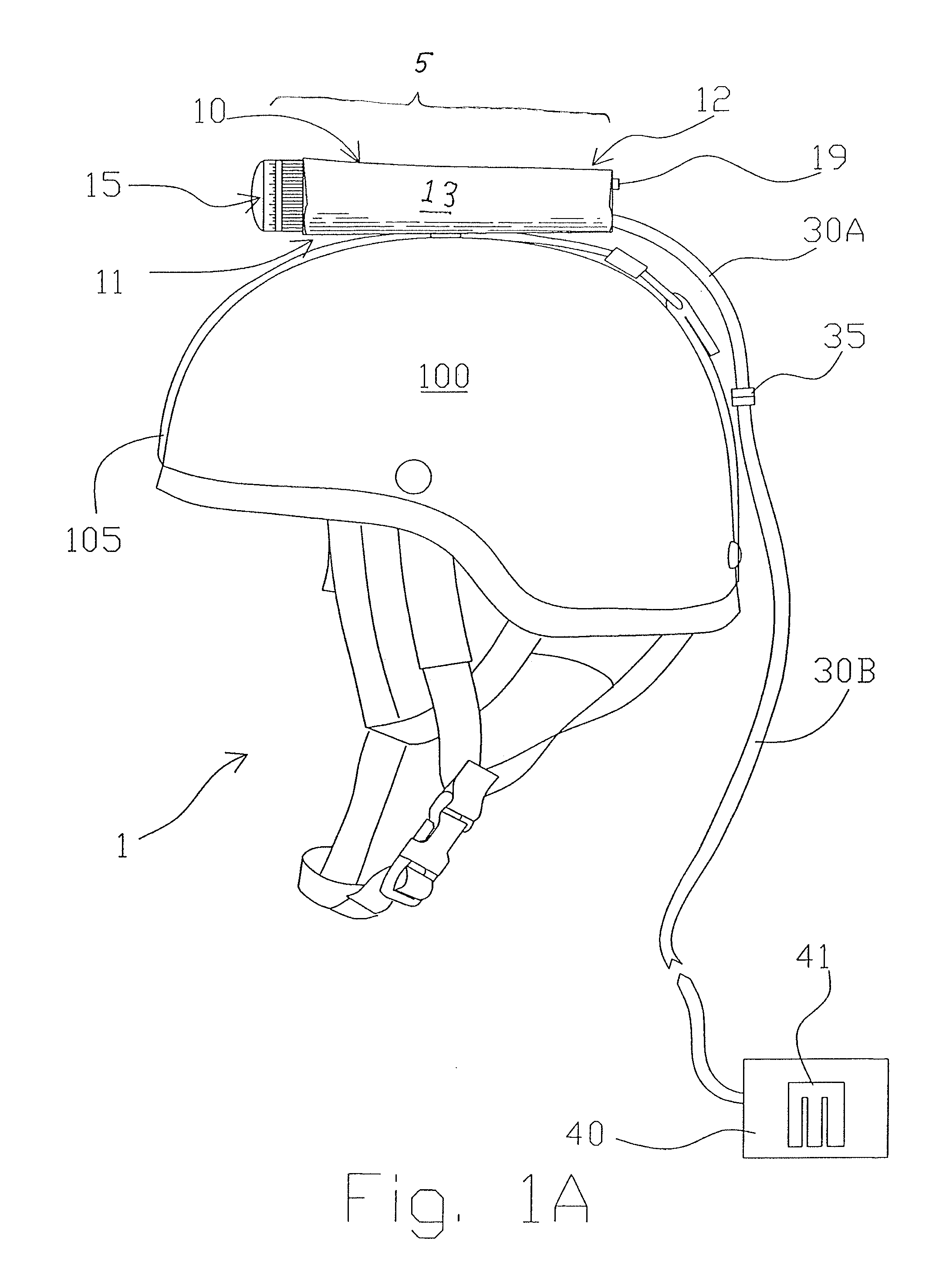
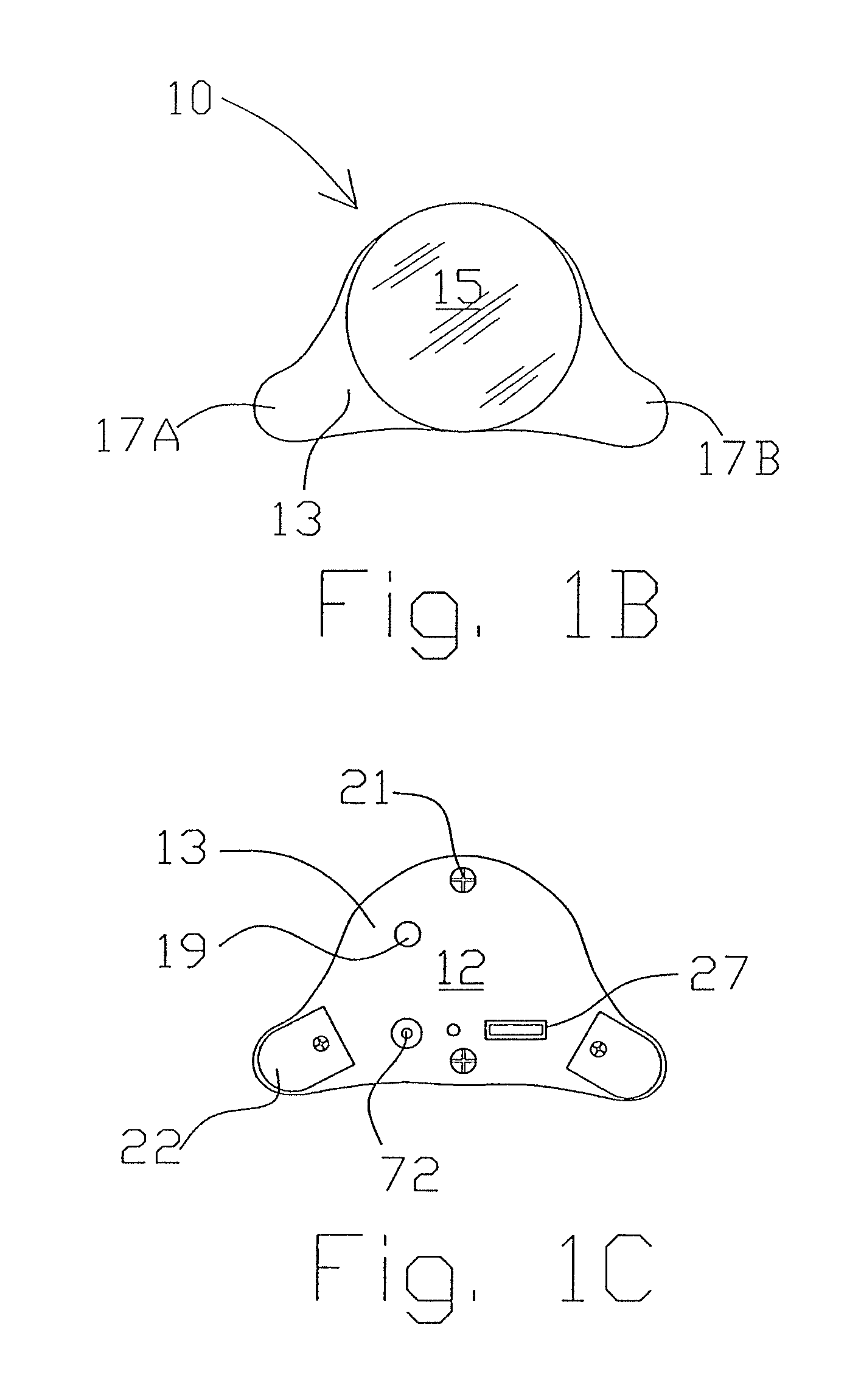
[0034]The embodiments of the invention and the various features and advantageous details thereof are more fully explained with reference to the non-limiting embodiments and examples that are described and / or illustrated in the accompanying drawings and set forth in the following description. It should be noted that the features illustrated in the drawings are not necessarily drawn to scale, and the features of one embodiment may be employed with the other embodiments as the skilled artisan recognizes, even if not explicitly stated herein. Descriptions of well-known components and techniques may be omitted to avoid obscuring the invention. The examples used herein are intended merely to facilitate an understanding of ways in which the invention may be practiced and to further enable those skilled in the art to practice the invention. Accordingly, the examples and embodiments set forth herein should not be construed as limiting the scope of the invention, which is defined by the appen...


PUM


Abstract

A night vision system includes an image sensor and circuitry coupled to a digital storage medium or transmitter that periodically samples a signal provided by the image sensor and stores the sampled image to be viewed in near real time or at a later date by a data analyst. The night vision system includes an imaging assembly with a casing surrounding an image intensifier and the associated circuitry along with a port for accepting a power and / or signal cable for providing power to the image assembly and image signal data to the digital storage medium. The system may further include a daytime camera and a switch for toggling the image signal data input to the digital storage medium between the daytime camera and the low light image sensor, as well as a transmission system for wirelessly transmitting signals.

Description

CROSS-REFERENCED TO RELATED APPLICATIONS[0001]This application is a continuation-in-part of application Ser. No. 12 / 589,695 filed, Oct. 27, 2009, which claims the benefit of provisional Application No. 61 / 197,259, filed Oct. 27, 2008, both of which are incorporated herein by referenceSTATEMENT REGARDING FEDERALLY SPONSORED RESEARCH OR DEVELOPMENT[0002]The present application did not receive any federal research and / or development funding.FIELD OF THE INVENTION[0003]Generally, the present invention relates to a night vision system deployed by an operator in a field environment. The system may be coupled onto the personal clothing, holsters, protective equipment, working animals such as dogs and their harness or remote devices or the like and used to capture images and store them onto a digital storage medium or transmit them through to remote location through cables or wirelessly. The system includes some type of low light or non-visible image capture device that converts night time ...

Claims


Application Information

Patent Timeline
Patent Type & Authority Patents(United States)
IPC IPC(8): H04N7/18
CPCH04N7/185G02B6/00G02B27/01G02B27/0149G02B27/0176G02B2027/0138H04N5/2254H04N5/23241H04N5/238H04N5/33H04N7/183H04N23/55H04N23/661H04N23/65H04N23/75
Inventor O'ROURKE, BRIAN
Owner DEVCAR
Why Eureka
Try Eureka