Shock absorber and suspension apparatus
a technology of shock absorber and suspension apparatus, which is applied in the direction of shock absorbers, mechanical devices, transportation and packaging, etc., can solve the problem that the semi-active suspension apparatus cannot generate and achieve the effect of generating a wide range of damping forces and keeping energy conservation
- Summary
- Abstract
- Description
- Claims
- Application Information
AI Technical Summary
Benefits of technology
Problems solved by technology
Method used
Image
Examples
first embodiment
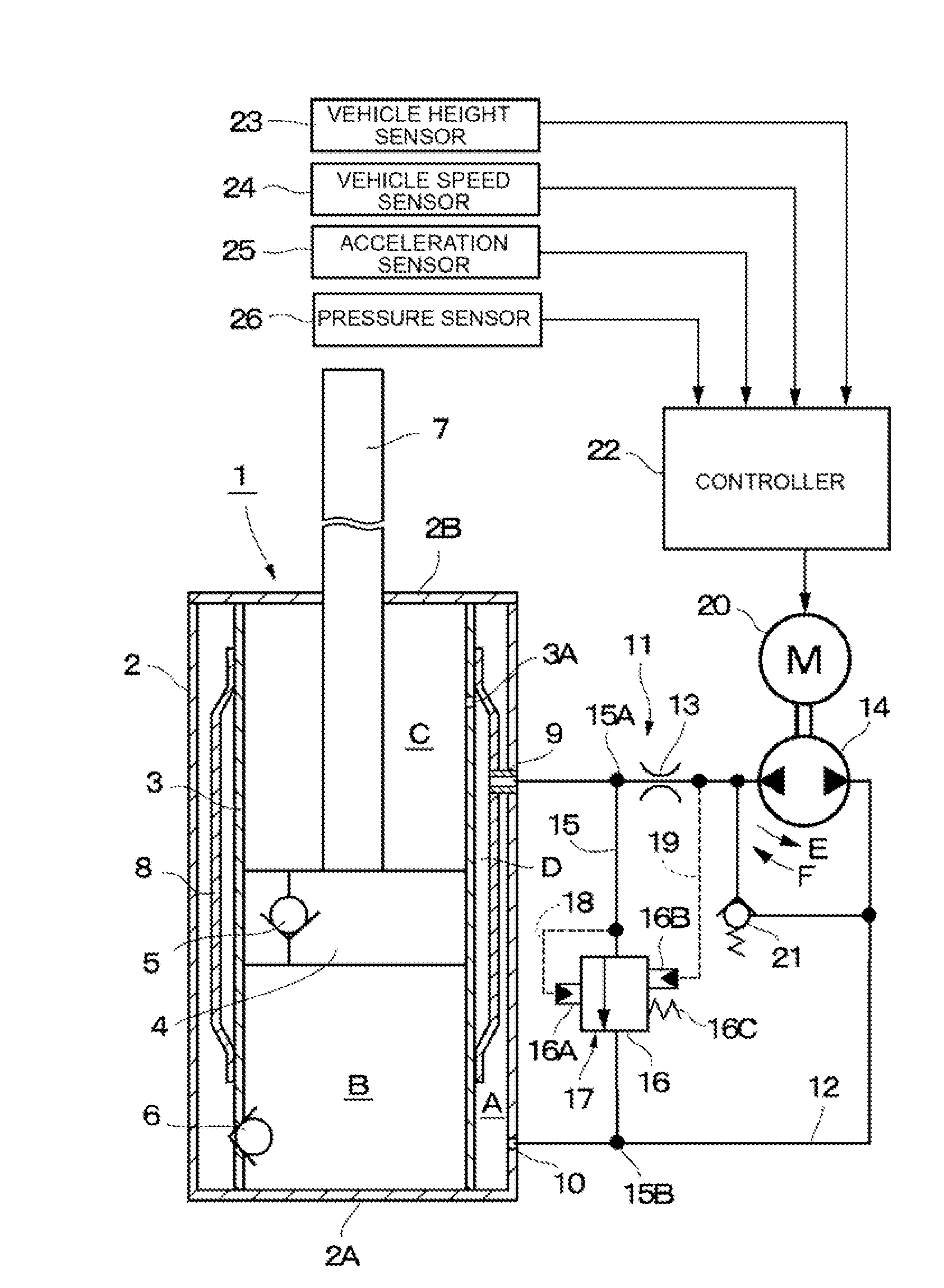
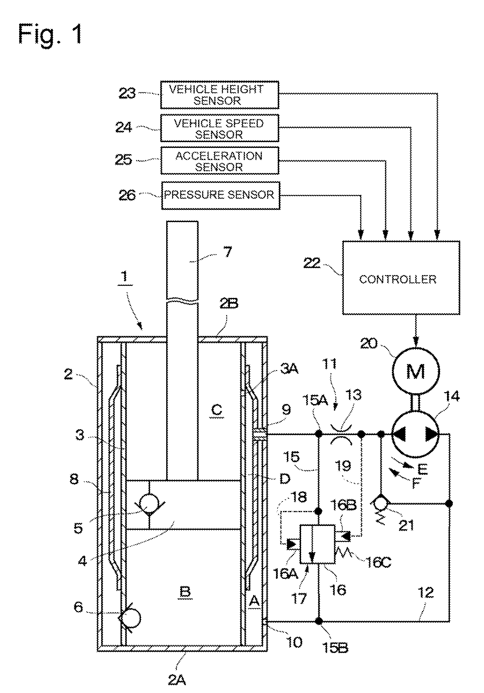
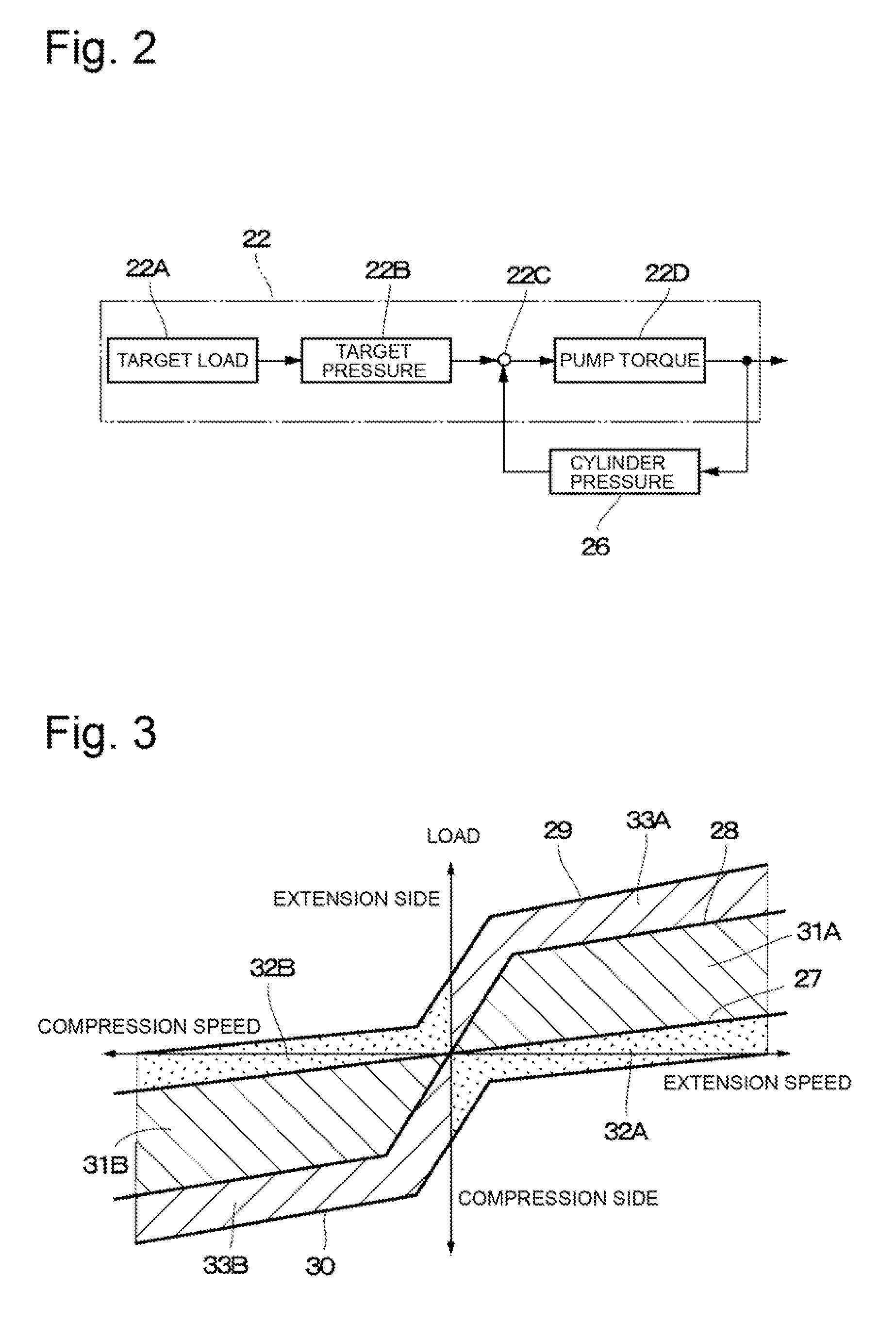
[0017]FIGS. 1 to 3 illustrate the present invention. In the figures, reference numeral 1 denotes a hydraulic cylinder as an example of at least one cylinder apparatus of the present invention and constituting a main body of a hydraulic shock absorber, and reference numeral 2 denotes a bottomed cylindrical outer tube constituting an outer shell of the hydraulic cylinder 1. The lower end side of the outer tube 2, which corresponds to one end side, is closed to define a bottom portion 2A. The upper end side of the outer tube 2, which corresponds to the other end side, is closed by a cover portion 2B. A rod guide, a seal (not-illustrated), and the like for slidably supporting a piston rod 7, which will be described later, are disposed at the inner circumferential side of the cover portion 2B.
[0018]Reference numeral 3 denotes an inner tube as a cylinder coaxially disposed in the outer tube 2. The inner tube 3 sealingly contains hydraulic fluid as operating fluid therein. The operating fl...
second embodiment
[0072]Reference numeral 50 denotes the second accumulator employed by the Like the above-described first accumulator 46, the second accumulator 50 constitutes the reservoir, and the interior thereof is divided into a gas chamber G and a hydraulic chamber H. However, the hydraulic chamber H of the second accumulator 50 is connected to the other side of the communication pipe line 49, and is also connected to the bypass pipe line 15 at the branch point 15B.
[0073]When the pump 14 is rotated in a normal direction indicated by an arrow E, the hydraulic fluid is discharged from the bottom-side hydraulic chamber B and the hydraulic passage 45 into the hydraulic chamber H of the second accumulator 50 via the communication pipe line 49, and the pilot pressure in the pilot chamber 16B is reduced via the pilot pipe line 19. Then, after the relief valve 16 is opened, the hydraulic fluid is also discharged into the hydraulic chamber H of the second accumulator 50 via the bypass pipe line 15.
[00...
third embodiment
[0084]However, the one end side 63A of the communication pipe line 63 is directly connected to the hydraulic passage 45 of the piston rod 7 in constant communication therewith. Further, the other end 63B of the communication pipe line 63 is connected to an accumulator 72, which will be described later. The pilot orifice 13 and the pump 14 are disposed at certain positions along the communication pipe line 63. The excessive load application prevention valve 21 is connected to the communication pipe line 63 at the upstream side and the downstream side of the pump 14 so as to be arranged in parallel with the pump 14.
[0085]The compression-side bypass pipe line 64 is connected to the communication pipe line 63 at branch points 64A and 64B to allow the pilot orifice 13 and the pump 14 to be bypassed. The relief valve 16 is disposed at a certain position along the bypass pipe line 64. The relief valve 16 constitutes the compression-side damping valve 65 together with the pilot orifice 13....
PUM
 Abstract
Description
Claims
Application Information
 - R&D
- Intellectual Property
- Life Sciences
- Materials
- Tech Scout
- Unparalleled Data Quality
- Higher Quality Content
- 60% Fewer Hallucinations
Browse by: Latest US Patents, China's latest patents, Technical Efficacy Thesaurus, Application Domain, Technology Topic, Popular Technical Reports.
© 2025 PatSnap. All rights reserved.Legal|Privacy policy|Modern Slavery Act Transparency Statement|Sitemap|About US| Contact US: help@patsnap.com


