Shock absorber and suspension apparatus

a technology of shock absorber and suspension apparatus, which is applied in the direction of shock absorbers, mechanical devices, transportation and packaging, etc., can solve the problem that the semi-active suspension apparatus cannot generate and achieve the effect of generating a wide range of damping forces and keeping energy conservation

Active Publication Date: 2012-12-06
HITACHI ASTEMO LTD
View PDF12 Cites 54 Cited by
  • Summary
  • Abstract
  • Description
  • Claims
  • Application Information

AI Technical Summary

Benefits of technology

[0006]An object of the present invention is to provide a shock absorber and a suspension apparatus capable of generating a wide range of damping forces while keeping energy conservation.

Problems solved by technology

However, the semi-active suspension apparatus cannot generate a wide range of damping forces compared to an active suspension apparatus configured to supply hydraulic fluid from the outside into a cylinder and discharge the hydraulic fluid from the cylinder to the outside, which leads to the necessity of further improvement of the semi-active suspension apparatus still now.

Method used


Image

  • Shock absorber and suspension apparatus
  • Shock absorber and suspension apparatus
  • Shock absorber and suspension apparatus

Examples


first embodiment

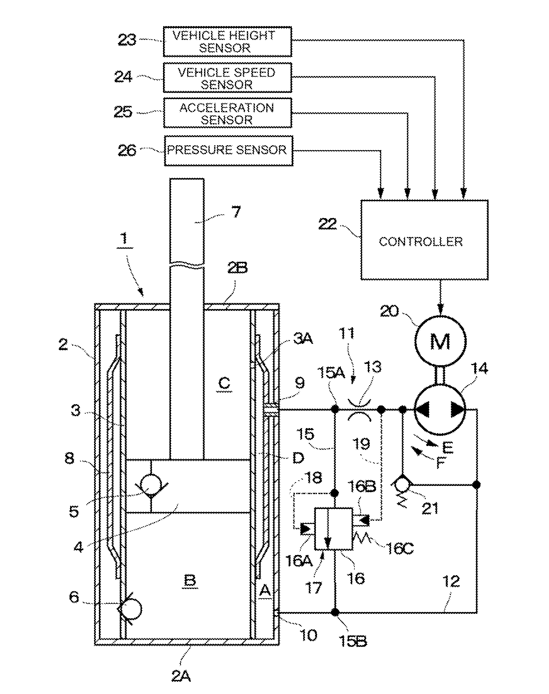
[0017]FIGS. 1 to 3 illustrate the present invention. In the figures, reference numeral 1 denotes a hydraulic cylinder as an example of at least one cylinder apparatus of the present invention and constituting a main body of a hydraulic shock absorber, and reference numeral 2 denotes a bottomed cylindrical outer tube constituting an outer shell of the hydraulic cylinder 1. The lower end side of the outer tube 2, which corresponds to one end side, is closed to define a bottom portion 2A. The upper end side of the outer tube 2, which corresponds to the other end side, is closed by a cover portion 2B. A rod guide, a seal (not-illustrated), and the like for slidably supporting a piston rod 7, which will be described later, are disposed at the inner circumferential side of the cover portion 2B.

[0018]Reference numeral 3 denotes an inner tube as a cylinder coaxially disposed in the outer tube 2. The inner tube 3 sealingly contains hydraulic fluid as operating fluid therein. The operating fl...

second embodiment

[0072]Reference numeral 50 denotes the second accumulator employed by the Like the above-described first accumulator 46, the second accumulator 50 constitutes the reservoir, and the interior thereof is divided into a gas chamber G and a hydraulic chamber H. However, the hydraulic chamber H of the second accumulator 50 is connected to the other side of the communication pipe line 49, and is also connected to the bypass pipe line 15 at the branch point 15B.

[0073]When the pump 14 is rotated in a normal direction indicated by an arrow E, the hydraulic fluid is discharged from the bottom-side hydraulic chamber B and the hydraulic passage 45 into the hydraulic chamber H of the second accumulator 50 via the communication pipe line 49, and the pilot pressure in the pilot chamber 16B is reduced via the pilot pipe line 19. Then, after the relief valve 16 is opened, the hydraulic fluid is also discharged into the hydraulic chamber H of the second accumulator 50 via the bypass pipe line 15.

[00...

third embodiment

[0084]However, the one end side 63A of the communication pipe line 63 is directly connected to the hydraulic passage 45 of the piston rod 7 in constant communication therewith. Further, the other end 63B of the communication pipe line 63 is connected to an accumulator 72, which will be described later. The pilot orifice 13 and the pump 14 are disposed at certain positions along the communication pipe line 63. The excessive load application prevention valve 21 is connected to the communication pipe line 63 at the upstream side and the downstream side of the pump 14 so as to be arranged in parallel with the pump 14.

[0085]The compression-side bypass pipe line 64 is connected to the communication pipe line 63 at branch points 64A and 64B to allow the pilot orifice 13 and the pump 14 to be bypassed. The relief valve 16 is disposed at a certain position along the bypass pipe line 64. The relief valve 16 constitutes the compression-side damping valve 65 together with the pilot orifice 13....


PUM


Abstract

A shock absorber includes: at least one cylinder apparatus including a cylinder sealingly containing operating fluid, a piston slidably fittedly inserted in the cylinder to divide an interior of the cylinder into two chambers, and a piston rod coupled to the piston and extending to an outside of the cylinder; and at least one damping force generation mechanism connected to the cylinder apparatus, and capable of generating a damping force to be applied to a flow of the operating fluid caused by a movement of the piston and adjusting the damping force from the outside. The damping force generation mechanism includes a damping valve for generating the damping force, a pilot chamber for applying a pilot pressure by the operating fluid to the damping valve, and a pump for at least supplying or discharging the operating fluid to or from the pilot chamber.

Description

BACKGROUND OF THE INVENTION[0001]1. Technical Field[0002]The present invention relates to a shock absorber and a suspension apparatus effectively usable to damp vibrations of, for example, an automobile.[0003]2. Background Art[0004]Generally, a vehicle, such as a two-wheeled or four wheeled motor vehicle, includes a hydraulic shock absorber disposed between a wheel side and a vehicle body side, and is configured to damp, for example, vertical vibrations generated when the vehicle is running by the shock absorber. There is known one type of such a shock absorber called semi-active suspension apparatus configured to variably control a damping force (for example, refer to Japanese Patent Public Disclosure No. 2009-281584).[0005]The semi-active suspension apparatus as a conventional shock absorber can variably control a damping force by controlling a hydraulic flow in a cylinder, thereby realizing energy conservation and a compact structure. However, the semi-active suspension apparatus...

Claims


Application Information

Patent Timeline
Patent Type & Authority Applications(United States)
IPC IPC(8): F16F9/50F16F9/19F16F9/06
CPCB60G17/08B60G2400/10B60G2500/10B60G2400/252B60G2400/51B60G2400/204
Inventor MORI, SHUNSUKENAKAMURA, KENICHI
Owner HITACHI ASTEMO LTD
Why Eureka
Try Eureka