Antenna equipment including the grouping of antenna elements according to communication types

a technology of communication types and antenna elements, applied in the field of antenna equipment, can solve problems such as difficulty in installing the required number of antennas

Inactive Publication Date: 2014-07-15
NTT DOCOMO INC
View PDF9 Cites 1 Cited by
  • Summary
  • Abstract
  • Description
  • Claims
  • Application Information

AI Technical Summary

Benefits of technology

[0006]The same array antenna is used for communications of different types, thereby eliminating the need for installing a required number of antennas for the communications. That is, fewer antennas need to be installed than before.

Problems solved by technology

However, it is difficult to install a required number of antennas for multi-antenna communication if available installation space is limited.

Method used


Image

  • Antenna equipment including the grouping of antenna elements according to communication types
  • Antenna equipment including the grouping of antenna elements according to communication types
  • Antenna equipment including the grouping of antenna elements according to communication types

Examples


first embodiment

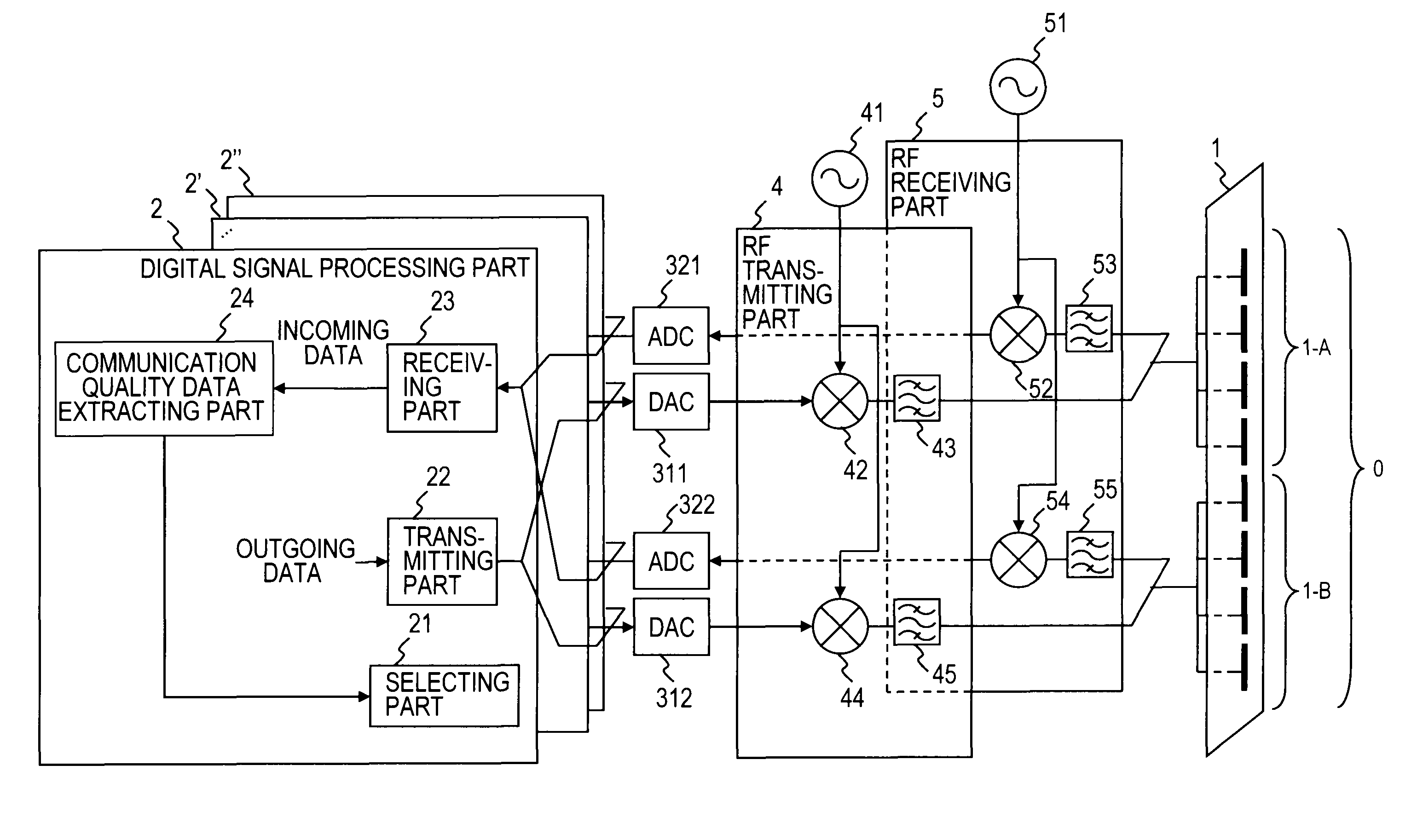
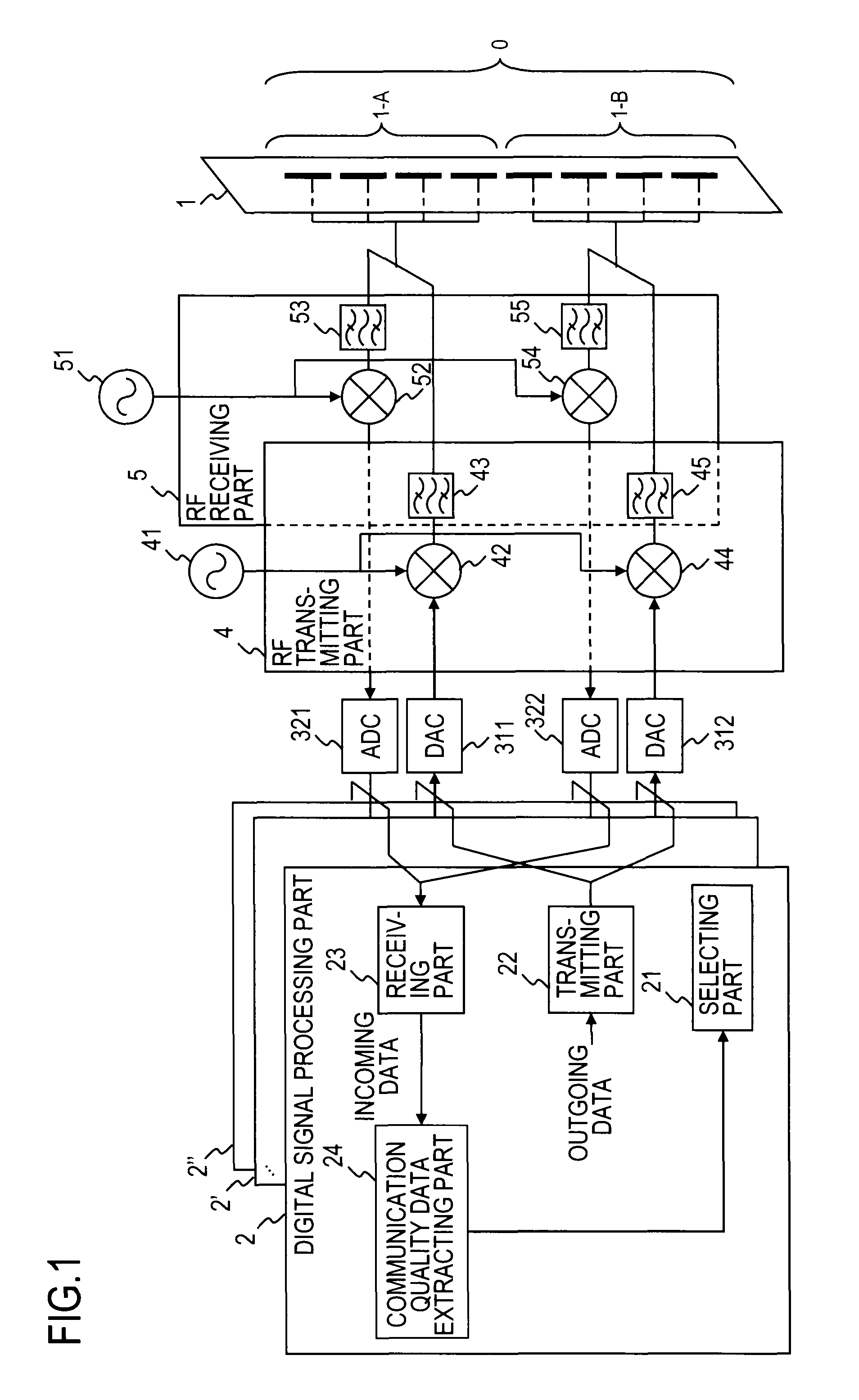
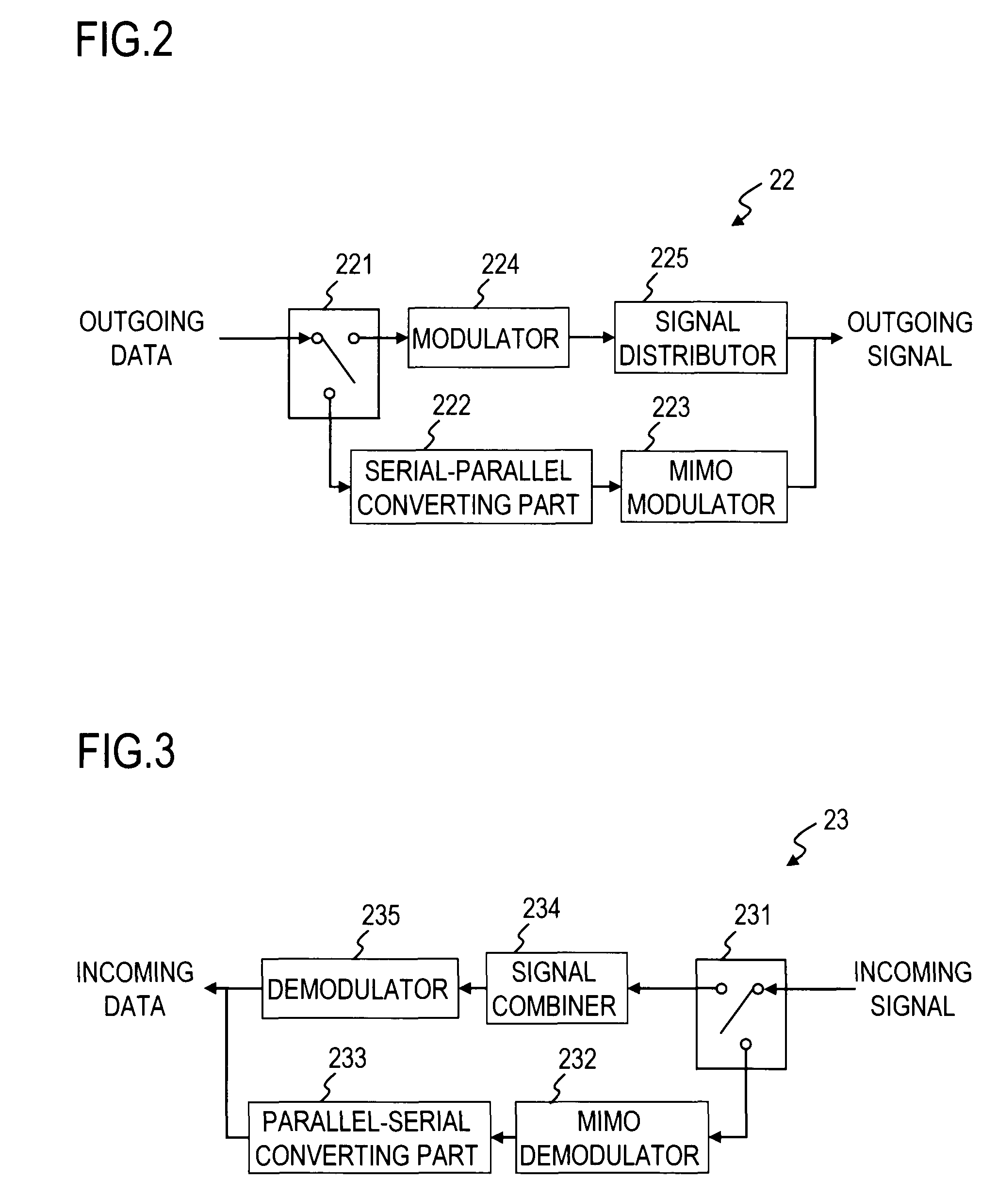
[0031]An antenna equipment of a first embodiment selects a set of one communication type and one group of antennas from two communication types and multiple groups of antenna elements according to the quality of communication with a mobile station. The antenna equipment uses the same array antenna to transmit and receive data to and from mobile stations. In the past, changing an existing SISO (Single-Input Single-Output) base station not supporting the MIMO transmission technology to a base station capable of using the MIMO has required installing array antennas equivalent to existing array antennas as many as or more than the number of MIMO branches in order to maintain an existing coverage area after the change. It is difficult to install array antennas as many as or more than the number of MIMO branches if space available for installing antennas is limited. Furthermore, reducing the size of array antennas to install more array antennas in order to provide required number of MIMO ...

second embodiment

[0058]The antenna equipment of the first embodiment selects one of the two communication types to perform communication whereas an antenna equipment of a second embodiment selects one from three communication types to perform communication. As in the second embodiment, one antenna equipment may support three or more communication types.

[0059]The following description will focus on differences from the first embodiment. Description of the same elements as those in the first embodiment will be omitted.

[0060]First and second communication types in the second embodiment are the same as those in the first embodiment. In the second embodiment, a third communication type is also available. The third communication type is MIMO 4×4 transmission.

[0061]For the third communication type, eight antenna elements making up an array antenna 1 are grouped into four groups: a group consisting of the first and second antenna elements 2-A from the top, a group consisting of the third and fourth antenna ...

third embodiment

[0068]As illustrated in FIG. 17, an antenna equipment of a third embodiment further includes a sub-array phase shifter 6 which adjusts the amount of phase shift of outgoing and incoming signals and a sub-array amplitude adjuster 7 which adjusts the amplitudes of outgoing and incoming signals. FIG. 17 illustrates an exemplary antenna equipment of the third embodiment which has a sub-array phase shifter 6 and a sub-array amplitude adjuster 7 in addition to the components of the antenna equipment of the first embodiment. The rest of the antenna equipment is the same as the antenna equipments of the first and second embodiments.

[0069]Here, the outgoing signal is a signal generated by a transmitting part 22 and the incoming signal is a signal from an analog-digital converting part.

[0070]The sub-array phase shifter 6 and the sub-array amplitude adjuster 7 adjust the phase and amplitude to desired values based on communication quality data extracted by a communication quality data extracti...


PUM


Abstract

An antenna equipment includes an array antenna including a plurality of antenna elements configured to be grouped into at least one group according to each of N communication types, where N is an integer greater than or equal to 2, a selecting part selecting one of the N communication types, a transmitting part modulating outgoing data to generate an outgoing signal for antenna element or antenna elements belonging to each group for the selected communication type, and a receiving part demodulating an incoming signal from antenna element or antenna elements belonging to each group for the selected communication type to generate incoming data.

Description

TECHNICAL FIELD[0001]The present invention relates to an antenna equipment used at wireless communication base stations and the like.BACKGROUND ART[0002]There are communication schemes that use multiple antennas. Example of such communication schemes includes MIMO (multiple-input multiple-output) transmission, communications using antenna diversity, and communications using beam forming. (For example, see “MIMO increases the transmission rate several-fold”, published on the Internet on Dec. 13, 2007 (retrieved on Aug. 5, 2010), <URL: http: / / itpro.nikkeibp.co.jp / article / COLUMN / 20071203 / 288625 / >).[0003]For such a multi-antenna communication scheme, as many antennas as required for the multi-antenna communication have been installed.[0004]However, it is difficult to install a required number of antennas for multi-antenna communication if available installation space is limited.SUMMARY OF THE INVENTION[0005]To solve the problem, an antenna equipment according to one aspect of the ...

Claims


Application Information

Patent Timeline
Patent Type & Authority Patents(United States)
IPC IPC(8): H04B1/38H01Q3/24H01Q3/26H01Q21/08H04B7/04H04B7/10H04J99/00
CPCH01Q21/061H01Q3/26H01Q21/28H01Q21/29H01Q1/246H04B7/0413H04B7/0691
Inventor INOUE, YUKICHO, KEIZO
Owner NTT DOCOMO INC
Why Eureka
Try Eureka