Fluid-filled type vibration damping device

a technology of vibration damping device and filling, which is applied in the direction of shock absorbers, machine supports, mechanical equipment, etc., can solve the problems of difficult to reduce the impact during the abutment, the possibility of striking noise during the abutment between the movable plate and the partition member, etc., to achieve the effect of vibration damping effect, avoiding increase in the number of components, and preventing the occurrence of nois

Active Publication Date: 2014-07-22
SUMITOMO RIKO CO LTD
View PDF18 Cites 11 Cited by
  • Summary
  • Abstract
  • Description
  • Claims
  • Application Information

AI Technical Summary

Benefits of technology

[0008]It is therefore one object of this invention to provide a fluid-filled type vibration damping device of novel construction which is able to switch the second orifice passage between open and closed states so as to obtain excellent vibration damping effect, as well as to reduce striking noise generated during switching the second orifice passage between open and closed states.

Problems solved by technology

However, with the fluid-filled type vibration damping device disclosed in JP-A-2007-155033, an impact during abutment of the movable rubber plate against the partition member may be transmitted as a noise to the vehicle body via the second mounting member.
Accordingly, a differential in fluid pressure between the pressure-receiving chamber and the equilibrium chamber is likely to exert on the movable plate as an accelerating force, so that possible striking noise during abutment between the movable plate and the partition member tends to be a problem.
This makes it difficult to reduce the impact during the abutment.

Method used


Image

  • Fluid-filled type vibration damping device
  • Fluid-filled type vibration damping device
  • Fluid-filled type vibration damping device

Examples


Embodiment Construction

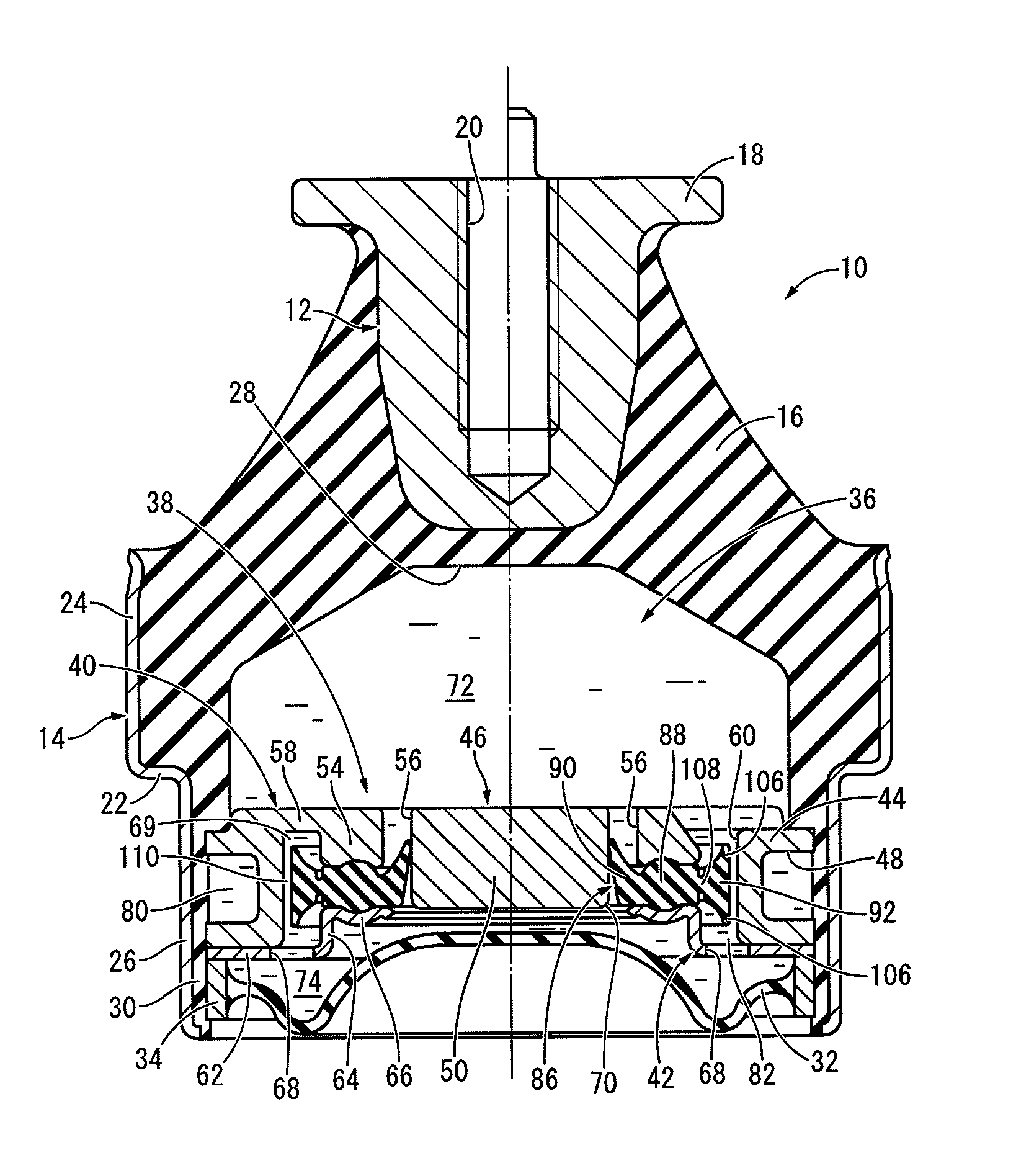
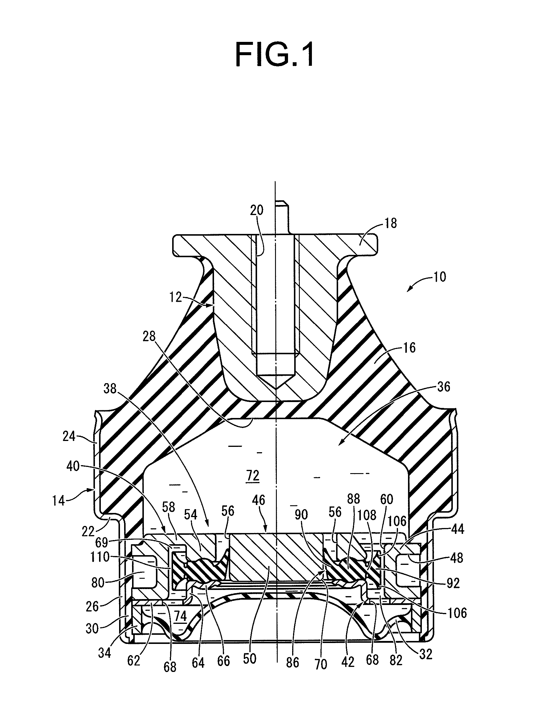
[0035]Referring first to FIG. 1, there is depicted an automotive engine mount 10 according to a first embodiment of a fluid-filled type vibration damping device constructed in accordance with the present invention. The engine mount 10 has a construction in which a first mounting member 12 and a second mounting member 14 are connected by a main rubber elastic body 16. In the description hereinbelow, as a general rule, the vertical direction refers to the vertical direction in FIG. 1, which coincides with the principal vibration input direction.

[0036]Described more specifically, the first mounting member 12 is a high rigidity component of small-diameter, generally circular post shape, and at its axially upper end, has a flange portion 18 that projects peripherally outward. The first mounting member 12 also has a bolt hole 20 that extends on the center axis and opens onto the upper face thereof. The bolt hole 20 is provided with a screw thread on its inside peripheral face.

[0037]The se...


PUM


Abstract

A fluid-filled type vibration damping device including an elastic movable member attached to a partition member. The elastic movable member includes a clasped portion clasped by the partition member and a switching portion provided to an outer peripheral side of the clasped portion and positioned within a second orifice passage. An abutting portion is provided to the switching portion and projects to lengthwise opposite sides of the orifice passage. A switching mechanism is constituted for opening the orifice passage through a gap formed between the switching portion and the inside face of the orifice passage while closing the orifice passage by abutment of the abutting portion against the inside face of the orifice passage by means of a tilting motion of the switching portion relative to the clasped portion through elastic deformation of a thin portion provided between the clasped portion and the switching portion.

Description

INCORPORATED BY REFERENCE[0001]The disclosure of Japanese Patent Application No. 2011-114388 filed on May 23, 2011 including the specification, drawings and abstract is incorporated herein by reference in its entirety. This is a Continuation of International Application No. PCT / JP2012 / 003328 filed on May 22, 2012.BACKGROUND OF THE INVENTION[0002]1. Field of the Invention[0003]The present invention relates generally to a fluid-filled type vibration damping device used for an automotive engine mount or the like. More particularly, the present invention pertains to a fluid-filled type vibration damping device capable of achieving vibration damping effect based on flow action of a fluid with respect to any of two or more vibration inputs having different frequencies.[0004]2. Description of the Related Art[0005]Conventionally, there is known a vibration damping device interposed between components that make up a vibration transmission system so as to elastically connect or elastically su...

Claims


Application Information

Patent Timeline
Patent Type & Authority Patents(United States)
IPC IPC(8): F16F13/00
CPCF16F13/08F16F13/06F16F13/18F16F13/106
Inventor ISHIKAWA, RYOTAOGAWA, YUICHIYOSHII, NORIAKI
Owner SUMITOMO RIKO CO LTD
Why Eureka
Try Eureka