
Electrical connector socket capable of transmitting different signals

a technology of electrical connectors and sockets, applied in the direction of electrical discharge lamps, coupling device connections, coupling protection earth/shielding arrangements, etc., can solve the problems of wasting considerable space on electronic devices and wasting space to install socket connectors

Inactive Publication Date: 2014-07-29
ADVANCED CONNECTION TECH
View PDF4 Cites 24 Cited by
  • Summary
  • Abstract
  • Description
  • Claims
  • Application Information

AI Technical Summary

Benefits of technology

The present invention is about a tongue plate of an insulating base used in electrical devices. It has two tongue parts connected to each other, which provides settings for different signal terminals. The second and fourth terminals are located on the front surface of the second tongue part. The second and fourth terminals are between the first and third groups of signal terminals. The fourth terminal has a transmitting body on the insulating base and is connected to the second and third terminals, which helps to match the impedance of the terminals. In simple terms, this invention allows for the transmission of multiple signals through the same device.

Problems solved by technology

Particularly when multiple electrical connectors conforming to different electronic signal transmission specifications need to be installed to provide plugging of different plug connectors, since the installation of each electrical connector necessarily occupy a certain volume, and the electrical connectors must be spaced from one another by intervals, the intervals cause a waste of space.
If an electronic device providing digital video entertainment needs a socket electrical connector conforming to a high-definition multimedia interface (HDMI) specification and a socket connector conforming to a universal serial bus (USB) specification, and also needs an earphone socket and a microphone socket, considerable space on the electronic device is wasted to install the socket connectors.
Consequently, there is still a need of integrating multiple electrical connectors such as external serial advanced technology attachment (ESATA) connectors, HDMI connectors, display-ports or USB connectors to save the occupied space while taking into consideration the configuration of each group of signal terminals and false plugging of different plug interfaces, which is a problem to be solved by relevant manufacturers involved in the industry.

Method used


Image

  • Electrical connector socket capable of transmitting different signals
  • Electrical connector socket capable of transmitting different signals
  • Electrical connector socket capable of transmitting different signals

Examples


Embodiment Construction

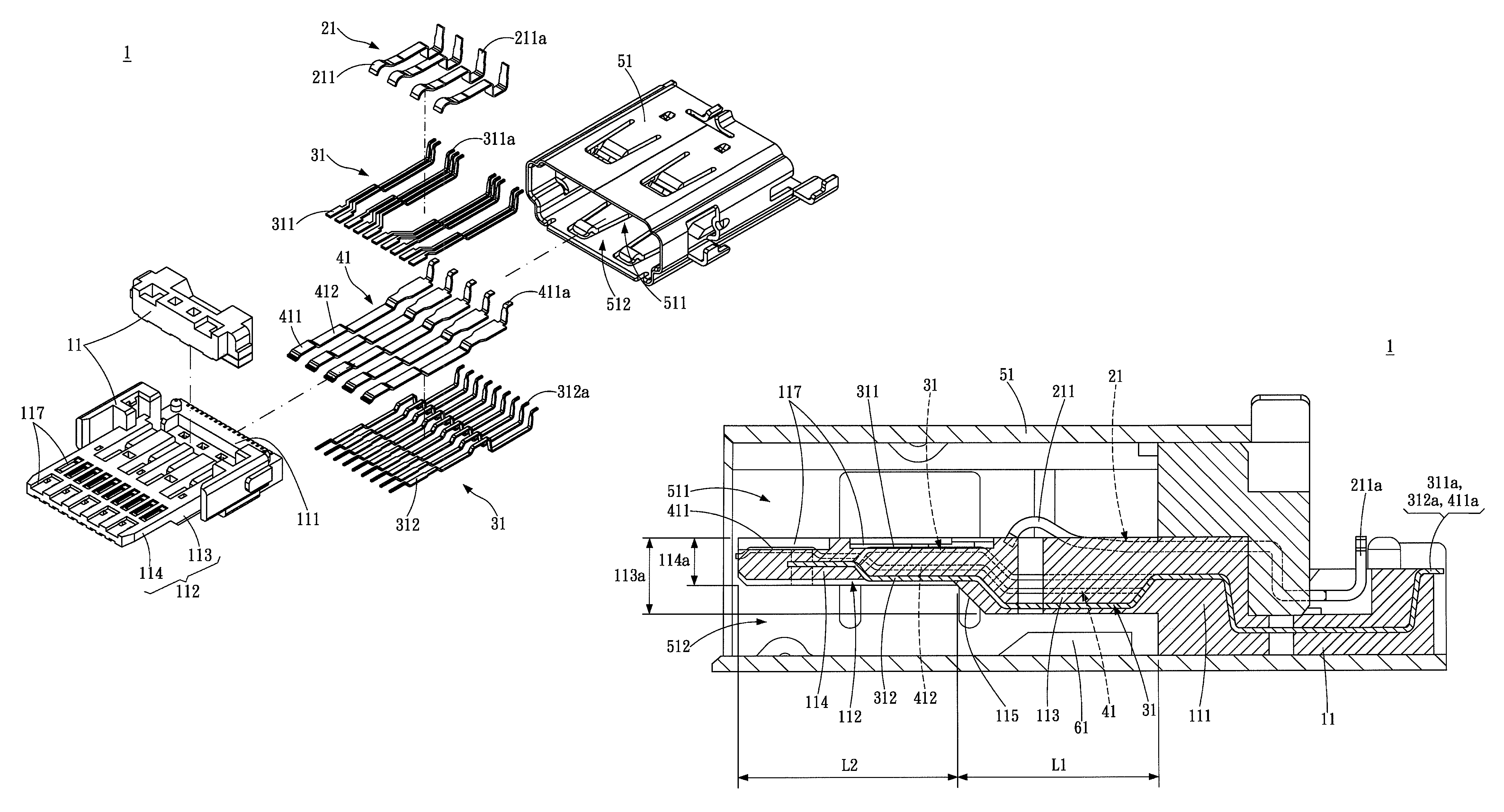
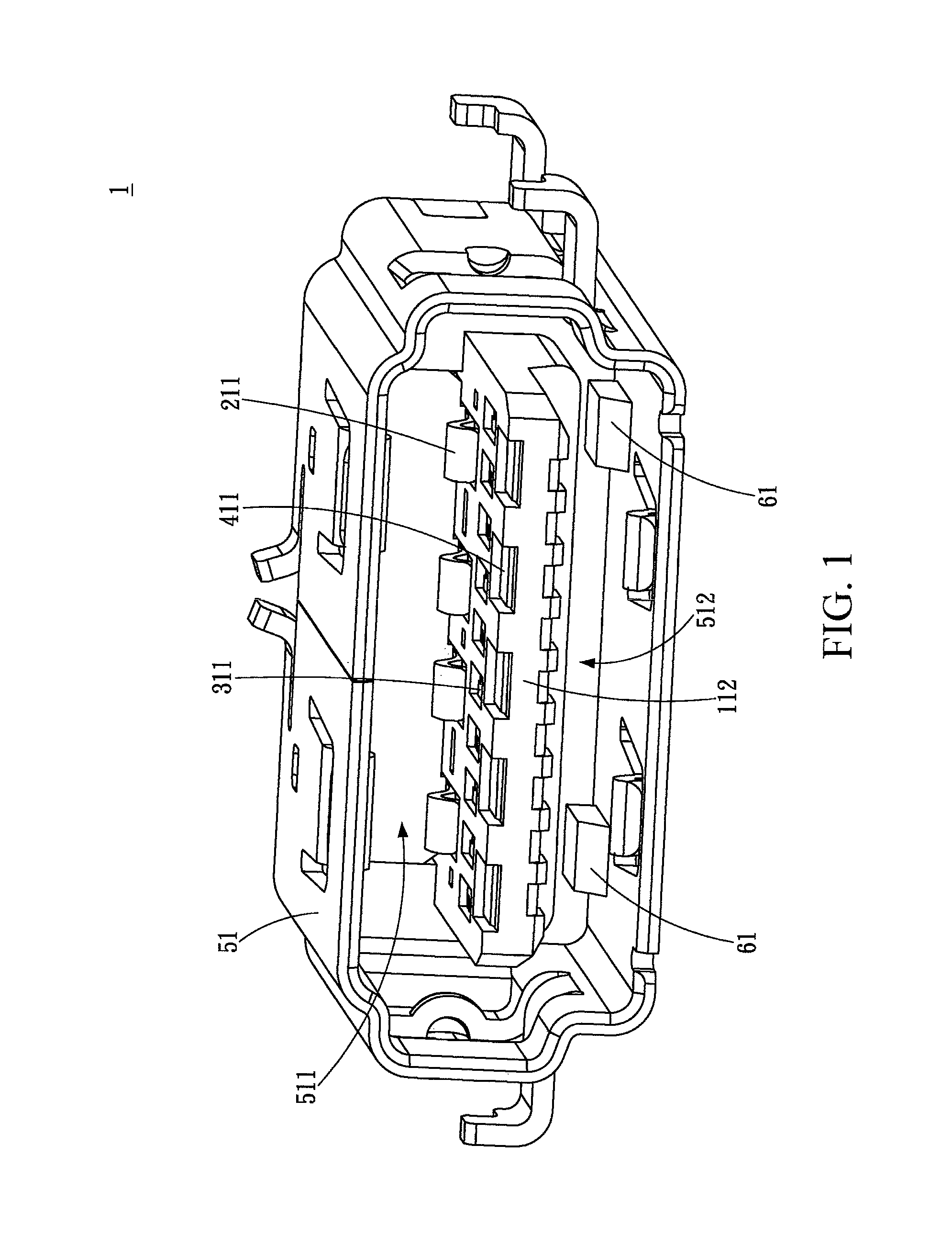
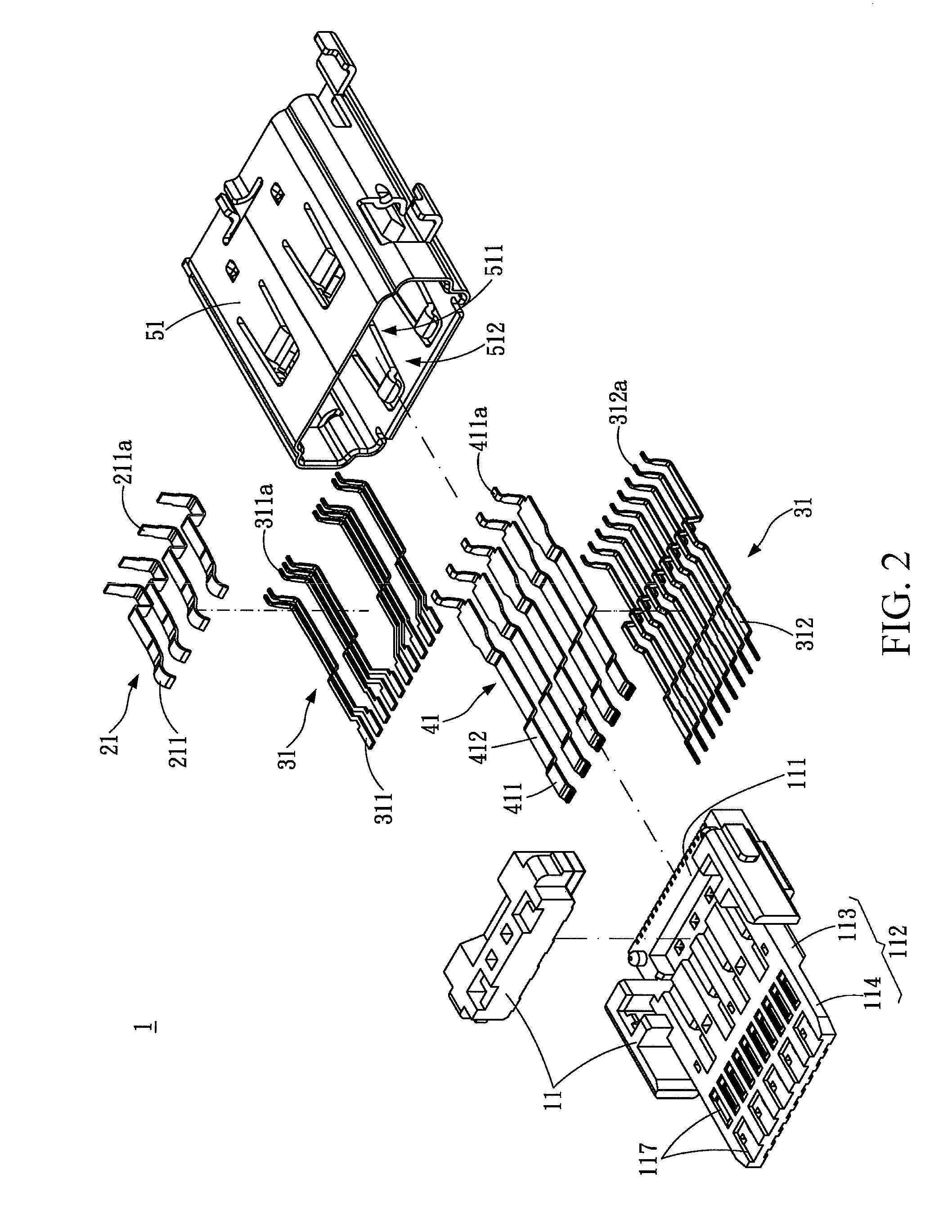
[0020]Please refer to FIGS. 1, 2, and 3, in which a first embodiment of the present invention is shown. FIG. 1 is a schematic outside view, FIG. 2 is a schematic exploded view, and FIG. 3 is a schematic cross-sectional view.

[0021]In the drawings of the first embodiment, an electrical connector socket 1 for plugging of at least two plugs (as shown in FIG. 7), with different specifications, is shown. In this embodiment, a first plug 81 for transmitting a USB2.0 signal and a second plug 82 for transmitting an HDMI signal are taken as an example for illustration; however, the transmission specifications of the first plug 81 and the second plug 82 are only exemplary, but the present invention is not limited thereto. The electrical connector socket 1 includes an insulating base 11, a first group of signal terminals 21, a second group of signal terminals 31, and a third group of signal terminals 41.

[0022]The insulating base 11 is made of a plastic material, and includes a main body 111 and...


PUM


Abstract

An electrical connector socket includes an insulating base, a first group of signal terminals, a second group of signal terminals, and a third group of signal terminals. The first group of signal terminals includes first terminals for transmitting a first signal. The second group of signal terminals includes second terminals and third terminals, and the second terminals and the third terminals are used for transmitting a second signal. The third group of signal terminals includes fourth terminals, the second terminals are located between the first group of signal terminals and the third group of signal terminals, the fourth terminals are used for transmitting a third signal, and the first group of signal terminals and the third group of signal terminals are used for transmitting a fourth signal.

Description

CROSS-REFERENCES TO RELATED APPLICATIONS[0001]This non-provisional application claims priority under 35 U.S.C. §119(a) on Patent Application No. 101210652 filed in Taiwan, R.O.C. on 2012 Jun. 1, the entire contents of which are hereby incorporated by reference.BACKGROUND OF THE INVENTION[0002]1. Technical Field[0003]The present invention relates to an electrical connector, and more particularly to an electrical connector socket capable of transmitting a plurality of different signals.[0004]2. Related Art[0005]Currently, electronic apparatuses are widely used. With electronic devices becoming increasingly light, thin, short, and small, the volume occupied by electrical connectors on the electronic devices must be reduced accordingly. Particularly when multiple electrical connectors conforming to different electronic signal transmission specifications need to be installed to provide plugging of different plug connectors, since the installation of each electrical connector necessarily ...

Claims


Application Information

Patent Timeline
Patent Type & Authority Patents(United States)
IPC IPC(8): H01R24/00
CPCH01R27/02H01R24/60
Inventor WANG, CHING-SHUNCHANG, CHIA-HOTANG, YUAN-BIN
Owner ADVANCED CONNECTION TECH
Learn More