
Optical waveguides having flattened high order modes

a waveguide and high-order mode technology, applied in the field of waveguides, can solve the problems achieve the effects of waveguide damage, reducing the threshold for undetected nonlinear propagation artifacts, and improving the efficiency of power guide packing

Active Publication Date: 2014-08-05
LAWRENCE LIVERMORE NAT SECURITY LLC
View PDF0 Cites 4 Cited by
  • Summary
  • Abstract
  • Description
  • Claims
  • Application Information

AI Technical Summary

Benefits of technology

The invention makes the stitched high-order mode more robust against nonlinear propagation defects and allows it to propagate at a different speed than neighboring modes. This makes it easier to cleanly excite and more efficient in packing power. The flattened sub-portions of the mode can also be designed to reduce nonlinear propagation artifacts or create unique patterns.

Problems solved by technology

This inherent advantage simplifies the task of selectively exciting and de-exciting a desired mode, but unfortunately a large fraction of the power guided by the high order circularly-symmetric modes of conventional waveguides tends to be located near the central axis of the waveguide, and this hot-spot may reduce the threshold for undesired nonlinear propagation artifacts and waveguide damage.

Method used


Image

  • Optical waveguides having flattened high order modes
  • Optical waveguides having flattened high order modes
  • Optical waveguides having flattened high order modes

Examples


Embodiment Construction

[0034]The present invention reduces the intensity of light propagating in the core of a preselected high-order propagation mode of a waveguide by distributing it more evenly across the guide's cross-section via careful design of the refractive index profile. The resulting high order mode is more robust to perturbation than is the fundamental mode of an equivalent conventional or flattened waveguide, and does not suffer the potentially problematic hot spots of conventional high order mode fibers.

[0035]The waveguides described here are presumed to be made of glass or of a material that allows light to propagate a suitable distance with a suitably low loss to meet the needs of its intended application.

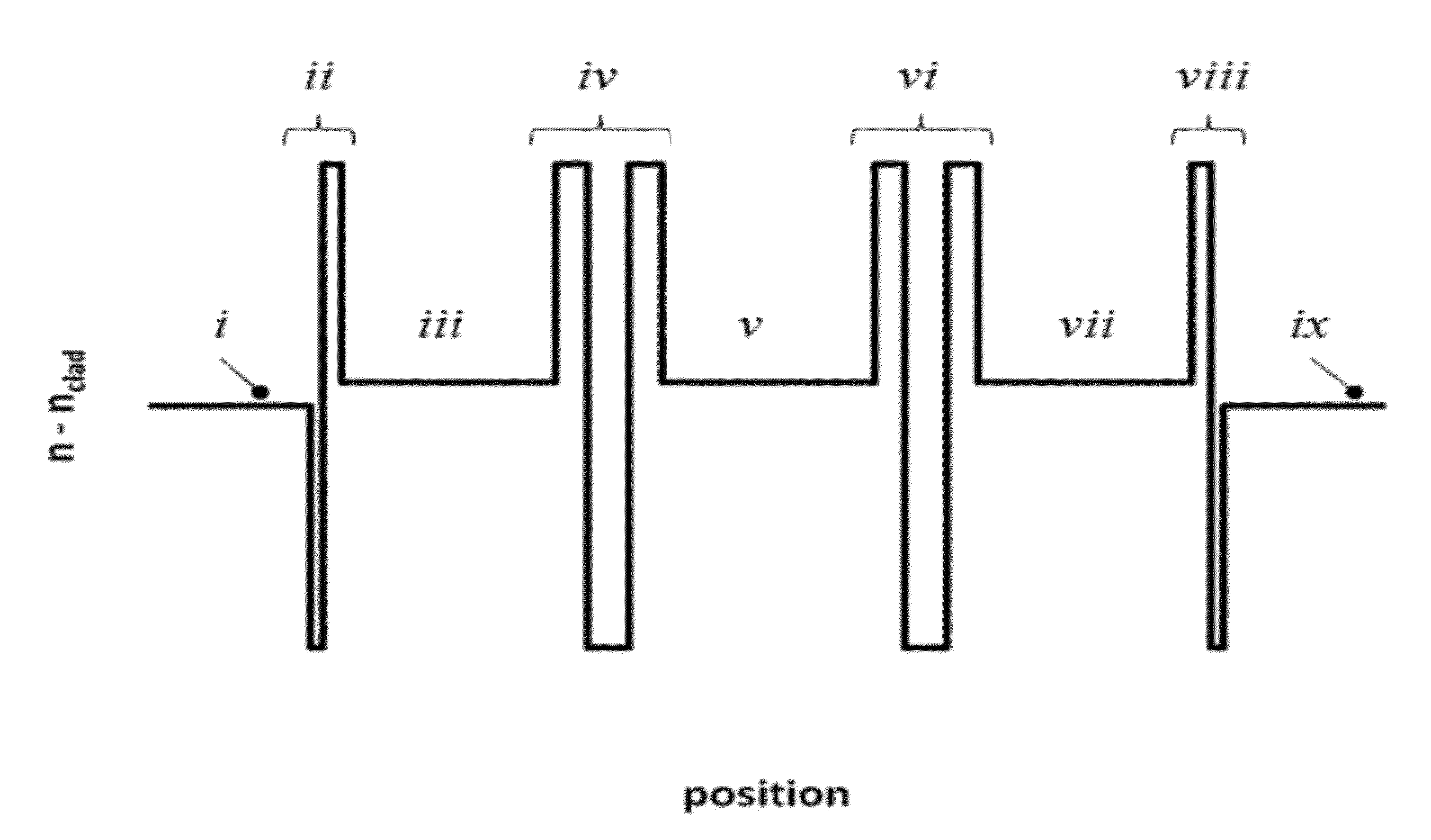
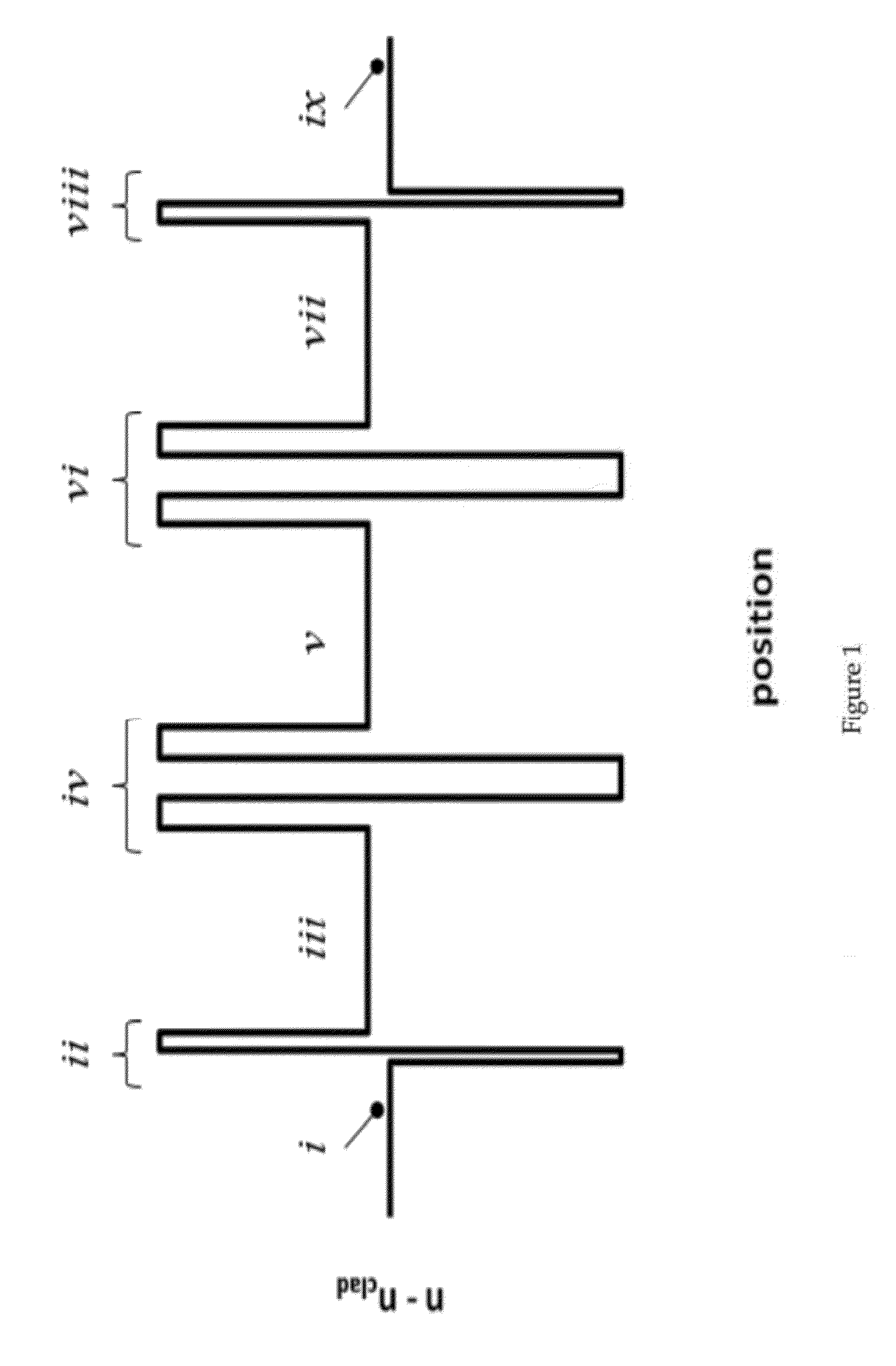
[0036]FIG. 1 illustrates the refractive index profile of a notional waveguide, showing flattening layers, stitching groups, and termination groups.

[0037]In general, the waveguide structure is chosen so that, over selected portions of its cross-section, the local refractive index is equal ...


PUM

PropertyMeasurementUnit
areaaaaaaaaaaa
refractive indexaaaaaaaaaa
polarityaaaaaaaaaa

Abstract

A deterministic methodology is provided for designing optical fibers that support field-flattened, ring-like higher order modes. The effective and group indices of its modes can be tuned by adjusting the widths of the guide's field-flattened layers or the average index of certain groups of layers. The approach outlined here provides a path to designing fibers that simultaneously have large mode areas and large separations between the propagation constants of its modes.

Description

STATEMENT REGARDING FEDERALLY SPONSORED RESEARCH OR DEVELOPMENT[0001]The United States Government has rights in this invention pursuant to Contract No. DE-AC52-07NA27344 between the U.S. Department of Energy and Lawrence Livermore National Security, LLC, for the operation of Lawrence Livermore National Laboratory.BACKGROUND OF THE INVENTION[0002]1. Field of the Invention[0003]The present invention relates to waveguides that propagate light at multiple discreet speeds—equivalently, multiple discreet transverse modes—and that transport telecommunications signals, generate or amplify light, transport electromagnetic power, or are used for decorative or display purposes.[0004]2. Description of Related Art[0005]Optical fiber waveguides that transport telecommunications signals are typically designed and manufactured to allow light to propagate at just one speed, to ensure that a signal arrives at its destination in a single, brief instant. Waveguides that generate or amplify light, such ...

Claims


Application Information

Patent Timeline
Patent Type & Authority Patents(United States)
IPC IPC(8): G02B6/036
CPCC03B37/01413C03B37/01211C03B37/01807C03B2203/22G02B6/0008G02B6/03605G02B6/03688G02B6/122
Inventor MESSERLY, MICHAEL JOSEPHBEACH, RAYMOND JOHNHEEBNER, JOHN EDWARDDAWSON, JAY WALTERPAX, PAUL HENRY
Owner LAWRENCE LIVERMORE NAT SECURITY LLC
Learn More