Waveguides having patterned, flattened modes

a waveguide and mode technology, applied in the field of waveguides, can solve the problems of affecting the performance and utility of the very system, affecting affecting so as to achieve the effect of improving the performance and utility of the system, and improving the efficiency of the power guid

Active Publication Date: 2015-10-27
LAWRENCE LIVERMORE NAT SECURITY LLC
View PDF3 Cites 42 Cited by
  • Summary
  • Abstract
  • Description
  • Claims
  • Application Information

AI Technical Summary

Benefits of technology

[0014]Yet another object is to extend the patterned flattened-mode concept to hexagonal geometries of uniform refractive index packed into hexagonal arrays. By changing the refractive index or thickness of a nominally hexagonal coating's layers along its perimeter, pure stack-and-draw methods can create strands and shells that are sufficiently flat for patterning, opening an attractive path to their fabrication.
[0017]Embodiments of the present waveguides consist of field-flattening strands located inside an encompassing field-flattening shell. The method can be applied to form modes that are more bend-tolerant than conventional modes of comparable size, or more tolerant of nonlinear defects such as nonlinear self-focusing. By applying this invention, the field of the patterned flattened mode can be made more robust to nonlinear propagation defects, and can be made to propagate at a speed that differs significantly from the speeds of its neighboring modes (when compared to the differences that naturally arise in conventional waveguides). The flattened field and / or larger speed differentials also make the higher order mode easier to cleanly excite than the same mode in a conventional guide. Other benefits are that the stitched high order mode waveguide can be designed to pack the power it guides very efficiently, and can be designed to avoid problematic hot spots in the field.
[0018]Exemplary uses of the invention include (i) the creation of rare earth-doped optical fibers having larger modes than can currently be manufactured and conveniently deployed, in order to allow lasers and amplifiers made from such fibers to handle increased power levels and pulse energies and (ii) the creation of large mode optical fibers to route very high laser powers or pulse energies within a structure. Other uses include (i) the creation of very large mode optical fibers for propagating telecommunications signals, where the large mode size allows stronger pulses to be propagated without incurring nonlinear artifacts, and to thus allow an increase in the spacing of repeaters in a communications network and (ii) the creation of optical fibers with aesthetically pleasing or unique modal structures to cosmetically differentiate products, or for entertainment or display purposes.
[0020]The parent application, U.S. patent application Ser. No. 13 / 162,351, filed Jun. 16, 2011, titled “Optical Waveguides Having Flattened High Order Modes,” incorporated herein by reference, describes methods for designing and manufacturing axially-symmetric waveguides that propagate a high-order, field-flattened mode—a mode with regions in which the field does not vary with azimuth or radius. It is believed that the structures placed into these guides better confine large modes and allow a mode's preferential guiding properties, such as its bend tolerance, to be tailored and better maintained as the guided mode size is increased.
[0021]Key features of the embodiments discussed herein include the following: The flattened modes do not suffer potentially problematic hotspots, they inherently pack the propagated power into a compact cross-section, and they may reduce a mode's susceptibility to some artifacts such as nonlinear self-focusing. In an amplifier, they allow power to be extracted uniformly and efficiently across the mode's cross-section. Furthermore, in amplifier applications, the stitching and termination groups would not likely be doped with rare-earth ions, allowing for better control of their indices, and since the field of the flattened mode is near-zero in those regions, avoiding leaving regions of unsaturated gain that might contribute to noise or amplification of undesired modes.
[0023]Comparisons to the high-order modes of a step-index fiber are complicated by the fact that the effective area, as conventionally defined, does not account for hotspots in a mode's peak irradiance. We have used the effective area metric here, but suggest that in some applications it may give an overly optimistic representation of the performance of high order step-index modes. Despite applying this possibly lenient metric, the high-order mode of the step-index example fiber is less attractive than the flattened modes in terms of intermodal spacing, peak irradiance, and the compactness of its mode. While increasing the v-number of the step-index design would improve the intermodal spacing, it would also increase its mode count, accentuate its central hotspot, and further reduce its mode's packing density.

Problems solved by technology

However, merely scaling the dimensions of optical fibers leads to systematic problems that can compromise the performance and utility of the very systems that they are intended to service.
Fibers with many higher-order modes result in “hot spots” in the guided optical beam, which can result in catastrophic optical damage and undesirable nonlinear optical effects.
In addition, fibers that support a large number of modes can limit the bandwidth (e.g., the data rate) of communication information.
Although functional in many applications, these large-area single-mode fibers are susceptible to bending losses.
These HOM fibers, can, in fact, result in a larger effective cross-sectional area, but, circularly symmetric versions suffer from hot spots that reduce the thresholds for nonlinear artifacts and damage.
As noted above, a major problem currently exists when scaling fibers (and waveguides) to support higher-order spatial modes, namely, that these structures can result in hot spots, which can lead to optical damage as well as undesirable nonlinear optical artifacts.
In conventional fibers, this state of affairs can lead to undesirable mode mixing, which can also limit the data rate and / or bandwidth in long-haul optical communication links.
This decrease in mode separation is undesirable in that it exacerbates modal mixing, which, as noted above, adversely affects the performance of fibers for beam delivery and communication purposes, among others.
Moreover, as the fiber scales in size, the presence of additional modes makes it more and more difficult to launch a beam into a single, desired guided mode without exciting undesirable neighboring modes.
While it is known that the high order modes of circularly symmetric waveguides have larger modal separations than the low order modes of these guides, the high order modes suffer from on-axis “hot spots” which may limit the power or energy those modes can carry, and this detriment may outweigh their modal separation benefit.
Specifically, these spatial intensity peaks can result in deleterious nonlinear propagation artifacts, which can induce power or energy to couple from a single desired HOM into other modes, degrading the quality of the beam emitted by the waveguide.
That is, the diffraction-limited spot size increases, with the result that the minimal focal size of the beam increases.
In addition, as the number of spatial modes increases, undesirable optical hot spots appear in the output beam.
However, those latter waveguides cannot practically achieve the large modal areas necessary for next generation applications, which, using the teachings herein, are now realizable, using the design rules described herein to realize fibers with field-flattened, single HOM configurations.

Method used


Image

  • Waveguides having patterned, flattened modes
  • Waveguides having patterned, flattened modes
  • Waveguides having patterned, flattened modes

Examples


example 1

Shell with a Single Strand

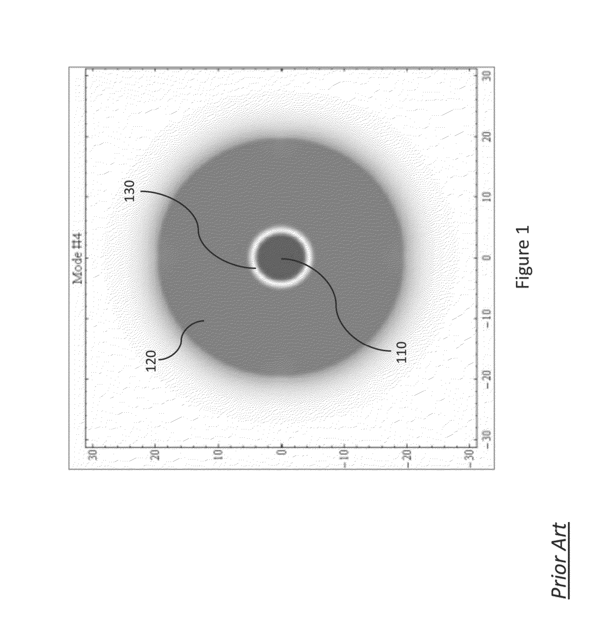
[0093]Turning now to FIG. 4, we show results of transverse field (not irradiance) profiles of several representative modes of a waveguide comprised of the Shell and Strand 1 parameters listed in Table 1. In this case, a single shell is filled with a single strand.

[0094]As depicted in the modal patterns of FIG. 4, field-flattened regions 410 and 420, respectively, represent different polarities of the field, and the grey-level shading corresponds its relative amplitude. The effective index decreases from the left column to the right, and the strand's shift increases from the top row to the bottom. All modal patterns are spatially scaled per the lower-left set of (scaled) axes, 430, and all quantities are dimensionless.

[0095]In the figure, each of the seven columns (each showing three patterns) corresponds to a specific modal field order (LP21, LP02, LP12, LP22 and LP03). On the other hand, each of the three rows (each showing seven patterns) corresponds to m...

example 2

Shell with Seven Strands

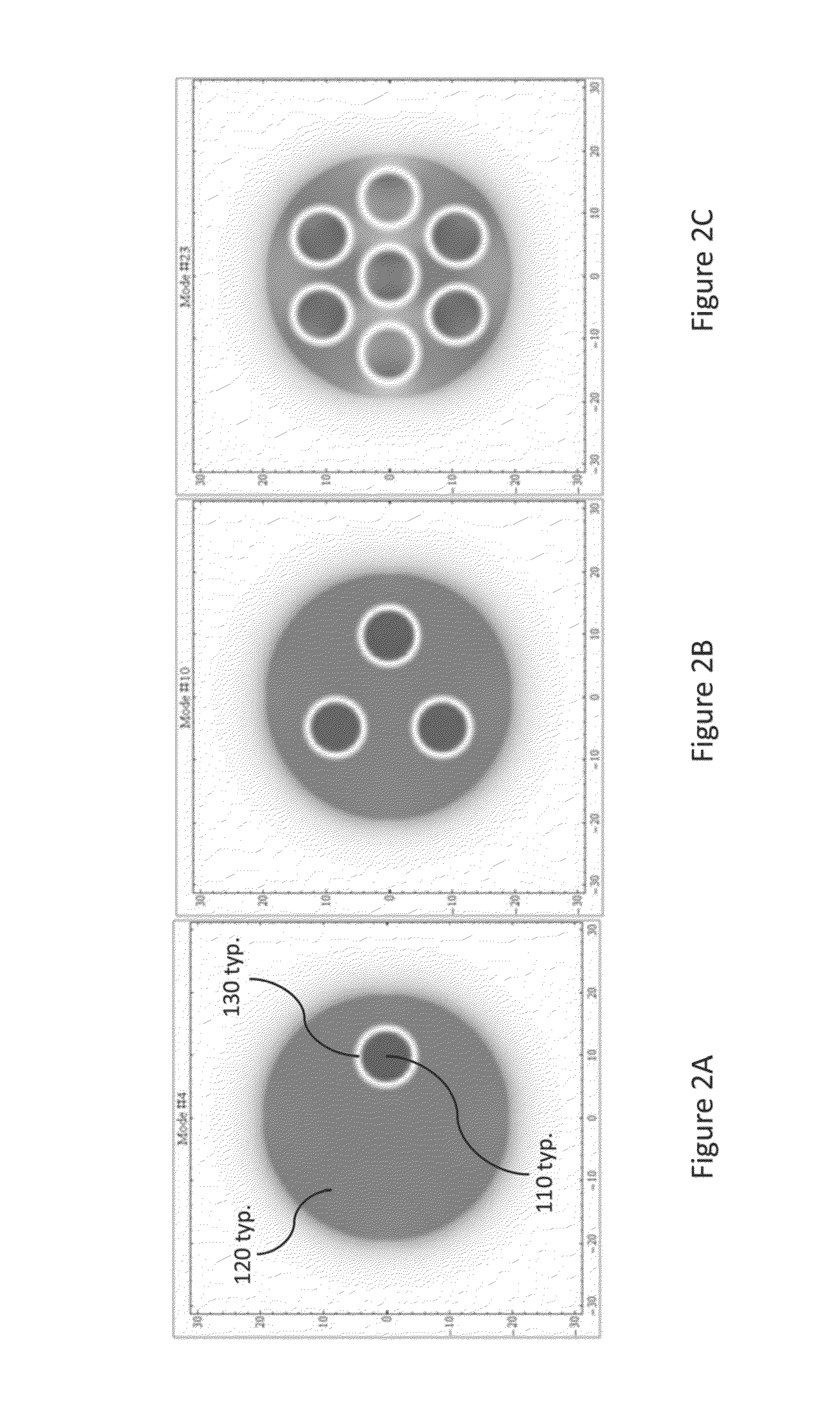
[0101]Turning now to FIG. 6, we show transverse field distributions (not irradiance profiles) of sixteen representative modes of a waveguide comprised of the Shell and Strand 2 parameters listed in Table 1. In this case, a single shell is filled with seven strands.

[0102]As depicted in the modal patterns of FIG. 6, field-flattened regions 610 and 620, respectively, represent different polarities of the field, and the grey-level shading corresponds its relative amplitude. All modal patterns are spatially scaled per the lower-left set of (scaled) axes, 630, and all quantities are dimensionless.

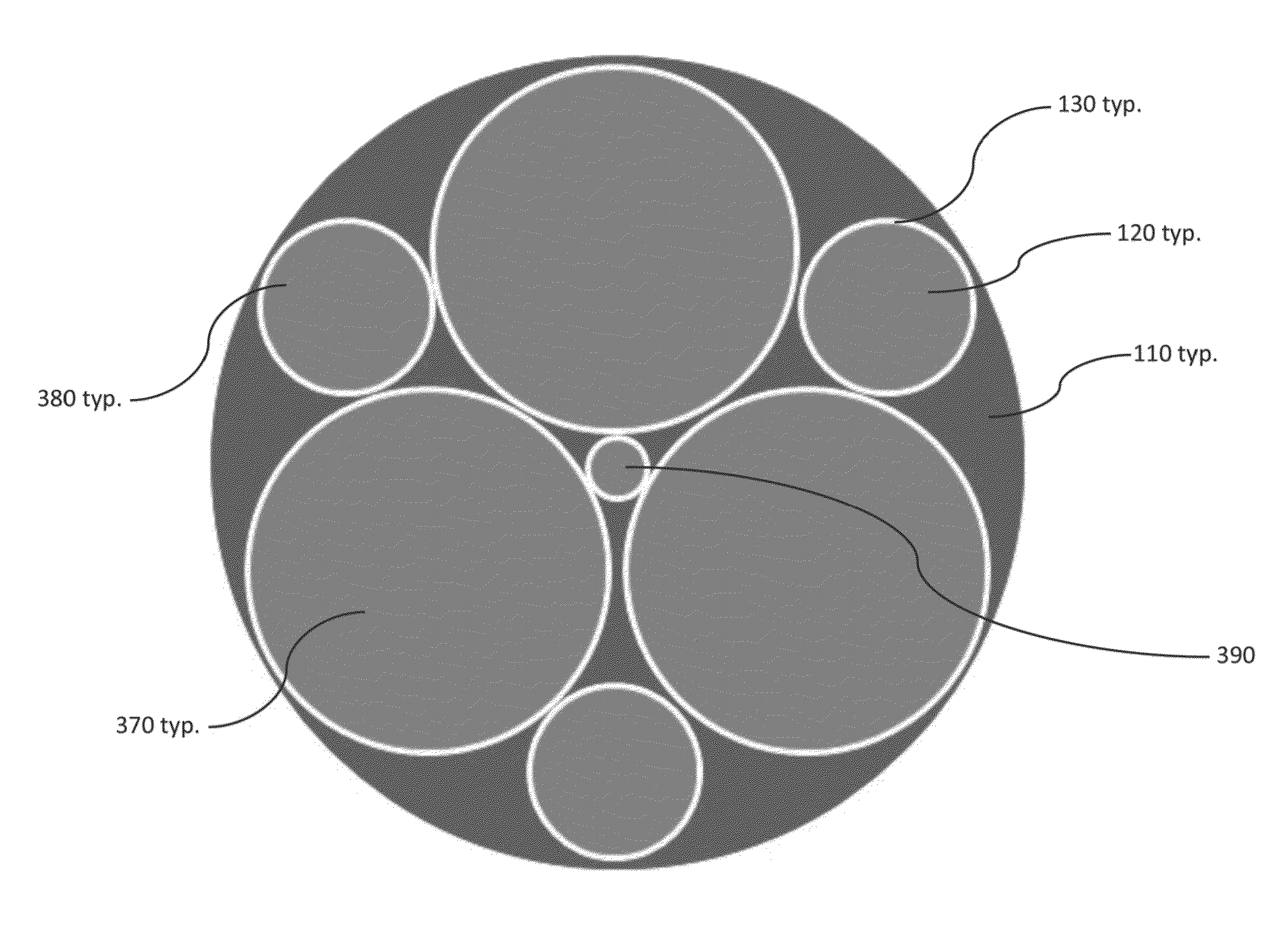
[0103]FIG. 6 also shows the transverse field profiles of 16 of the 28 non-degenerate modes allowed by a waveguide comprised of the Shell and seven strands of Strand 2 listed in Table 1. One strand is placed at the guide's center and six are placed at a radial distance of Δv=1.3π at 60° increments. For mode (i) the field's polarity changes sign from the center of the shell ...


PUM

PropertyMeasurementUnit
sizeaaaaaaaaaa
diameteraaaaaaaaaa
refractive indexaaaaaaaaaa

Abstract

Field-flattening strands may be added to and arbitrarily positioned within a field-flattening shell to create a waveguide that supports a patterned, flattened mode. Patterning does not alter the effective index or flattened nature of the mode, but does alter the characteristics of other modes. Compared to a telecom fiber, a hexagonal pattern of strands allows for a three-fold increase in the flattened mode's area without reducing the separation between its effective index and that of its bend-coupled mode. Hexagonal strand and shell elements prove to be a reasonable approximation, and, thus, to be of practical benefit vis-à-vis fabrication, to those of circular cross section. Patterned flattened modes offer a new and valuable path to power scaling.

Description

CROSS-REFERENCE TO RELATED APPLICATIONS[0001]This application is a continuation-in-part of U.S. patent application Ser. No. 13 / 162,351, filed Jun. 16, 2011, titled “OPTICAL WAVEGUIDES HAVING FLATTENED HIGH ORDER MODES,” incorporated herein by reference.STATEMENT REGARDING FEDERALLY SPONSORED RESEARCH OR DEVELOPMENT[0002]The United States Government has rights in this invention pursuant to Contract No. DE-AC52-07NA27344 between the U.S. Department of Energy and Lawrence Livermore National Security, LLC, for the operation of Lawrence Livermore National Laboratory.BACKGROUND OF THE INVENTION[0003]1. Field of the Invention[0004]The present invention relates to waveguides that propagate light at multiple, yet discrete speeds—equivalently, multiple discrete transverse modes—and that transport telecommunications signals, generate or amplify light, transport electromagnetic power, or are used for decorative or display purposes.[0005]2. Description of Related Art[0006]For optical fiber laser...

Claims


Application Information

Patent Timeline
Patent Type & Authority Patents(United States)
IPC IPC(8): G02B6/02H01S3/067C03B37/018C03B37/014C03B37/012F21V8/00
CPCG02B6/02338H01S3/06741C03B37/01211C03B37/01413C03B37/01807C03B2203/22G02B6/0008G02B6/02G02B6/02042
Inventor MESSERLY, MICHAEL J.PAX, PAUL H.DAWSON, JAY W.
Owner LAWRENCE LIVERMORE NAT SECURITY LLC
Why Eureka
Try Eureka