Electromagnetic induction heating fixing apparatus and image forming apparatus having the same

a technology of induction heating fixing and image forming, which is applied in the direction of electrographic process apparatus, instruments, optics, etc., can solve the problems of increasing the time required until the fixing belt is sufficiently heated, and it is difficult so as to shorten the warm-up time of the fixing belt. , to achieve the effect of reducing the overheating of the fixing bel

Inactive Publication Date: 2014-08-05
KYOCERA DOCUMENT SOLUTIONS INC
View PDF9 Cites 0 Cited by
  • Summary
  • Abstract
  • Description
  • Claims
  • Application Information

AI Technical Summary

Benefits of technology

[0009]The object of the present disclosure is to provide a function for suppressing overheating of a fixing belt, while shortening a belt warm-up time.

Problems solved by technology

However, although a conventional fixing apparatus is able to suppress overheating outside the paper passage region of the fixing belt, it is difficult to shorten the warm-up time of the fixing belt.
If the amount of heat transfer is large, then the time required until the fixing belt is sufficiently heated increases.

Method used


Image

  • Electromagnetic induction heating fixing apparatus and image forming apparatus having the same
  • Electromagnetic induction heating fixing apparatus and image forming apparatus having the same
  • Electromagnetic induction heating fixing apparatus and image forming apparatus having the same

Examples


first embodiment

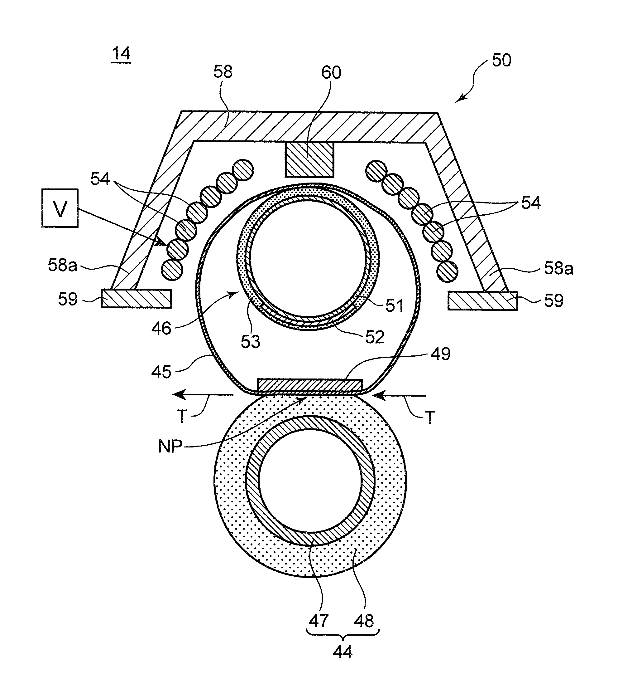
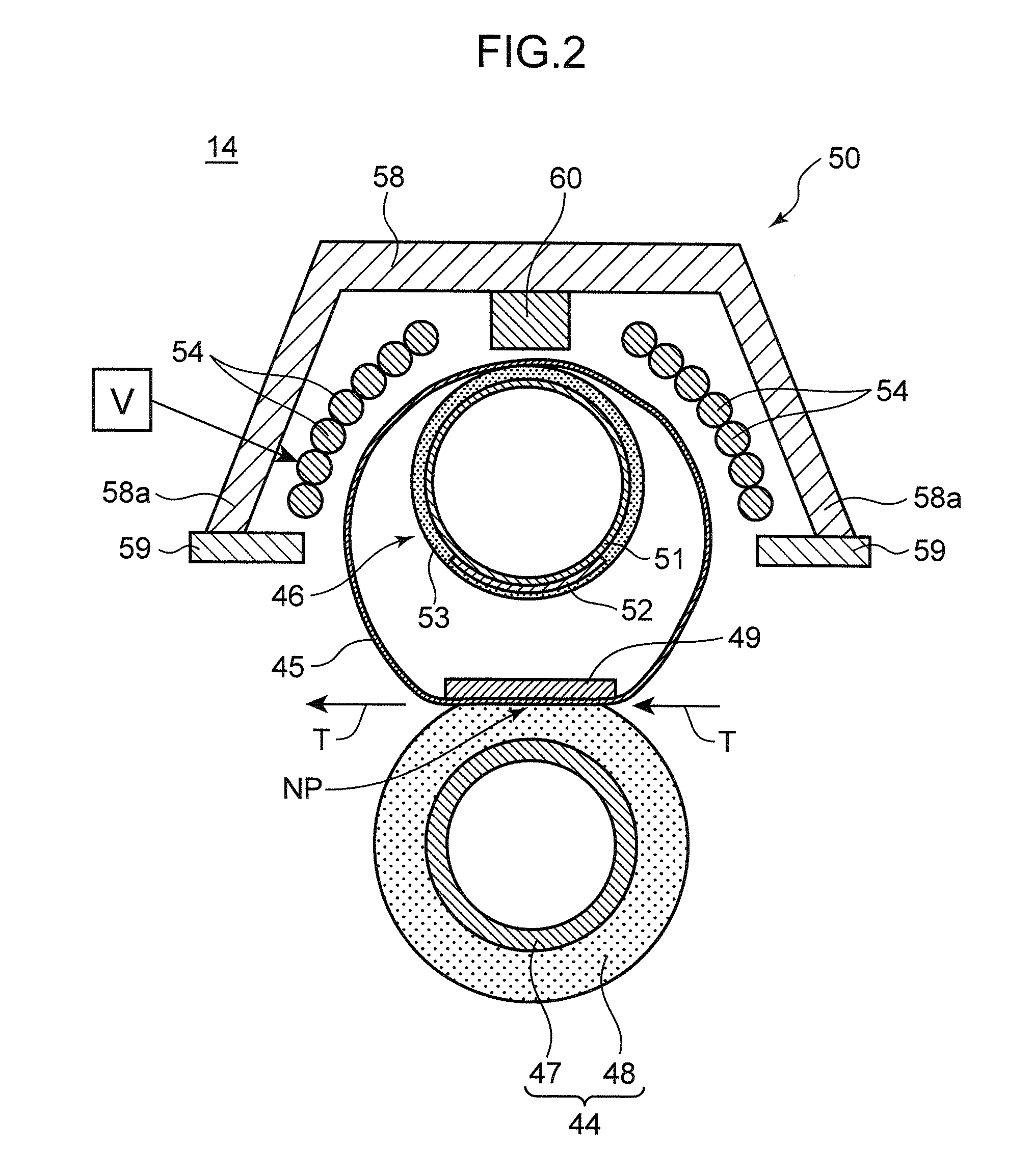
[0032]Next, a fixing apparatus 14 relating to a first embodiment is described with reference to FIG. 2. FIG. 2 is a vertical cross-sectional diagram of a fixing apparatus 14. The fixing apparatus 14 carries out a fixing process for fixing a toner image to a sheet T, by applying heat and pressure to the toner image which has been transferred to the sheet T. The fixing apparatus includes a pressurization roller 44 (rotating body), a fixing belt 45 (endless belt), a gripping piece 49, a heat value adjustment member 46, and a coil unit 50.

[0033]The pressurization roller 44 is a roller member capable of rotating in the counter-clockwise direction in FIG. 2, and is constituted by a tubular stainless steel core member 47, a silicone rubber elastic layer 48 which is laminated onto the core member 47, and a PFA surface separating layer (not illustrated), which is laminated onto the elastic layer 48. A heat source, such as a halogen heater, may be arranged inside the core member 47. The elast...

second embodiment

[0065]Next, a fixing apparatus 140 relating to a second embodiment is described with reference to FIG. 5. FIG. 5 is a vertical cross-sectional diagram of a fixing apparatus 140. Similarly to the fixing apparatus 14 according to the first embodiment, the fixing apparatus 140 includes a pressurization roller 44, a fixing belt 45, a gripping piece 49, a heat value adjustment member 61, and a coil unit 50. In the fixing apparatus 140 according to the second embodiment, only the composition of the heat value adjustment member 61 differs from that of the fixing apparatus 14 according to the first embodiment, and therefore description of the other members is omitted here.

[0066]In the fixing apparatus 140 according to the second embodiment, the heat value adjustment member 61 adjusts the amount of heat generated in the fixing belt 45 by generating heat itself. The heat value adjustment member 61 includes a base member 62 and a heat generating plate 63.

[0067]The base member 62 is a member ha...

third embodiment

[0084]Next, a third embodiment of the disclosure is described with reference to FIG. 8 and FIG. 9. FIG. 8 is a longitudinal cross-sectional diagram of the fixing apparatus 150 relating to a third embodiment, and shows a state where a magnetic shielding plate 52 is positioned in a restricting shielding position. FIG. 9 is a longitudinal cross-sectional diagram of the fixing apparatus 150 relating to a third embodiment, and shows a state where a magnetic shielding plate 52 is positioned in a shielding position.

[0085]Similarly to the fixing apparatus 14 according to the first embodiment, the fixing apparatus 150 according to the third embodiment includes a pressurization roller 44, a fixing belt 45, a gripping piece 49, a heat value adjustment member 46, and a coil unit 50. In the fixing apparatus 150 according to the third embodiment, only the composition of the heat value adjustment member 46 differs from that of the fixing apparatus 14 according to the first embodiment, and therefor...


PUM


Abstract

A fixing apparatus includes: a magnetic flux generating source which generates a magnetic flux; an endless belt which inductively generates heat by the magnetic flux while rotating in a prescribed direction; a rotating body which rotates in a prescribed direction and, together with the belt, forms a nip section through which a recording medium carrying a toner image passes; a core which is made of a magnetic material, and directs the magnetic flux to the belt; a heat value adjustment member for adjusting an amount of heat generated in the belt; and a gripping piece which is a non-rotating member, is disposed in a position corresponding to the nip section, and contacts an inner surface of the belt to rotatably grip the belt against the rotating body. The belt is wrapped between the heat value adjustment member and the gripping piece.

Description

BACKGROUND OF THE INVENTION[0001]1. Field of the Invention[0002]The present disclosure relates to a fixing apparatus which heats a toner image that has been transferred to a recording medium and thereby fixes the toner image onto the recording medium, and to an image forming apparatus using such a fixing apparatus.[0003]2. Description of the Related Art[0004]The basic constituent elements of an image forming apparatus such as a copying machine, a facsimile machine or a printer include: an image forming section which forms a toner image on an image carrying body (for example, a photosensitive drum); a transfer unit which transfers the toner image on the image carrying body to a sheet, which is one example of a recording medium; and a fixing apparatus which heats and fixes the toner image transferred to the sheet, onto the sheet.[0005]A growing number of fixing apparatuses employ a belt system in which the heat capacity can be set to a low value with a view to shortening the warm-up t...

Claims


Application Information

Patent Timeline
Patent Type & Authority Patents(United States)
IPC IPC(8): G03G15/20
CPCG03G15/2064G03G15/2053G03G2215/2038
Inventor GON, SYOUKOU
Owner KYOCERA DOCUMENT SOLUTIONS INC
Why Eureka
Try Eureka