Control device for internal combustion engine

a control device and internal combustion engine technology, applied in the direction of electric control, ignition automatic control, machines/engines, etc., can solve the problem of catalyst overheating in the exhaust passage, and achieve the effect of suppressing the catalyst overheating and reducing the number of injections

Active Publication Date: 2017-03-02
TOYOTA JIDOSHA KK
View PDF6 Cites 0 Cited by
  • Summary
  • Abstract
  • Description
  • Claims
  • Application Information

AI Technical Summary

Benefits of technology

[0015]With this configuration, it is possible to suppress an increase in the number of times of injection.
[0016]According to the aspect of the disclosure, it is possible to perform retardation of the ignition timing early while suppressing overheating of the catalyst.

Problems solved by technology

In such an internal combustion engine, when the ignition timing is retarded, the exhaust gas temperature increases so that there is a possibility that a catalyst disposed in an exhaust passage may be overheated.

Method used


Image

  • Control device for internal combustion engine
  • Control device for internal combustion engine
  • Control device for internal combustion engine

Examples


Embodiment Construction

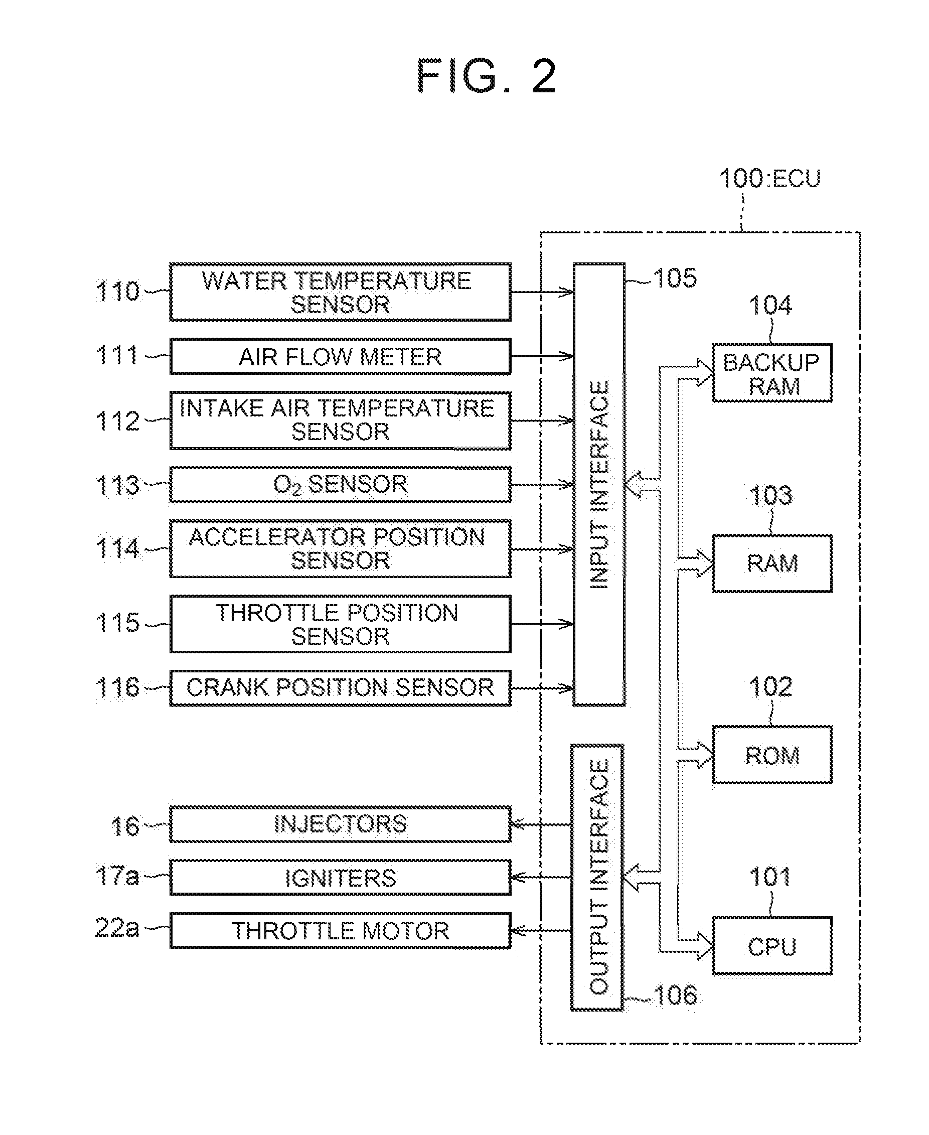
[0023]Hereinbelow, an embodiment of the disclosure will be described with reference to the drawings. In this embodiment, a description will be given of a case where the disclosure is applied to an Electronic Control Unit (ECU) that controls an internal combustion engine mounted on a vehicle.

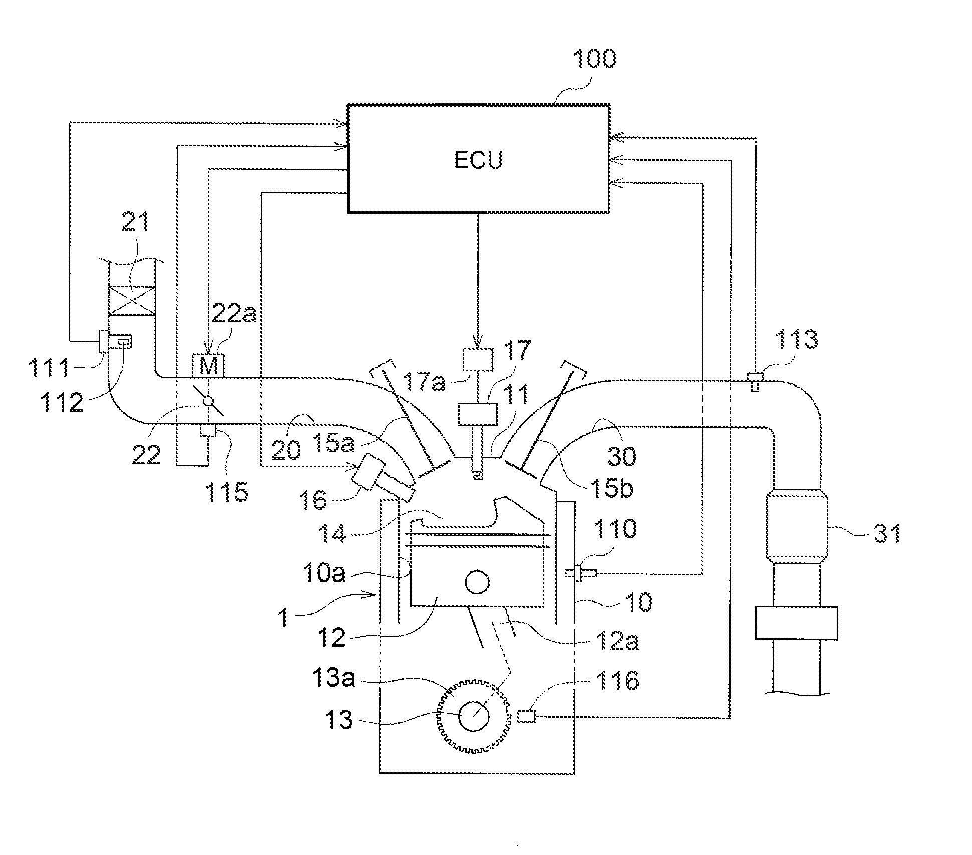
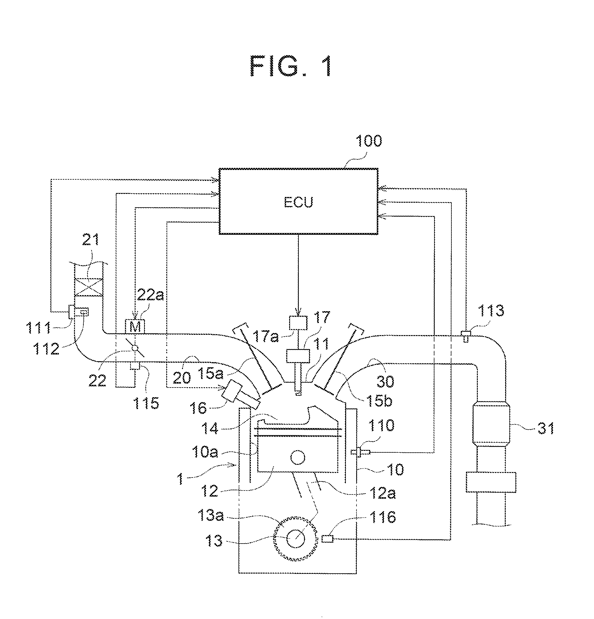
[0024]First, retelling to FIG. 1, a schematic configuration of an internal combustion engine 1 controlled by an ECU 100 will be described.

[0025]As shown in FIG. 1, the internal combustion engine 1 includes a cylinder block 10 and a cylinder head 11 mounted en the cylinder block 10. The internal combustion engine 1 is, for example, a direct-injection inline four-cylinder gasoline engine. In FIG. 1, only one of four cylinders its shown.

[0026]Four cylinder bores 10a are formed in the cylinder block 10 and a piston 12 is reciprocatingly disposed in each of the cylinder bores 10a. A crankshaft 13 as an output shaft is connected to the pistons 12 via connecting rods 12a. The connecting rod 12a has a fu...


PUM


Abstract

A control device for an internal combustion engine capable of performing additional injection in addition to regular injection includes an electronic control unit. The electronic control unit is configured to calculate an ignition timing at a predetermined crank angle before a compression top dead center. The electronic control unit is configured to calculate an injection amount of fuel at a predetermined time interval and to calculate an injection amount of the fuel at the predetermined crank angle. The electronic control unit is configured to control the fuel injection valve such that the fuel injection valve additionally injects the fuel in an increase amount before ignition, when the injection amount calculated at the predetermined crank angle is increased due to retardation of the ignition tinting calculated after the fuel in the injection amount calculated at the predetermined time interval is regularly injected.

Description

INCORPORATION BY REFERENCE[0001]The disclosure of Japanese Patent Application No. 2015-172598 filed on Sep. 2, 2015 including the specification, drawings and abstract is incorporated herein by reference in its entirety.BACKGROUND OF THE INVENTION[0002]1. Field of the Invention[0003]The invention relates to a control device for an internal combustion engine.[0004]2. Description of Related Art[0005]An internal combustion engine is known that retards the ignition timing for performing the torque down or the like. In such an internal combustion engine, when the ignition timing is retarded, the exhaust gas temperature increases so that there is a possibility that a catalyst disposed in an exhaust passage may be overheated. In view of this an internal combustion engine has been proposed that suppresses overheating of a catalyst by increasing the fuel injection amount when retarding the ignition timing (see, e.g. Japanese Patent Application Publication No. 2013-249792 (JP 2012-249792 A)). ...

Claims


Application Information

Patent Timeline
Patent Type & Authority Applications(United States)
IPC IPC(8): F02D41/40F02D41/02F02P5/04F02D43/04F02P5/15
CPCF02D41/402F02D43/04F02P5/1502F02D2041/0265F02D41/0235F02D2041/389F02D2200/0804F02P5/045F02D37/02F02D2200/0802F02D2250/12Y02T10/40
Inventor IWASAKI, RYOTAIDOGAWA, MASANAOKURODA, RYUSUKE
Owner TOYOTA JIDOSHA KK
Why Eureka
Try Eureka