Gas fueling method

a fueling method and gas technology, applied in the direction of battery/fuel cell control arrangement, process and machine control, instruments, etc., can solve the problems of insufficiently lowering the temperature of hydrogen gas using the pre-cooler, hydrogen tank overheating over an anticipated temperature, and disadvantageous increase of the fixed value used for a period of time as described above, so as to achieve the effect of suppressing the overheating of the tank

Active Publication Date: 2021-10-05
HONDA MOTOR CO LTD
View PDF14 Cites 0 Cited by
  • Summary
  • Abstract
  • Description
  • Claims
  • Application Information

AI Technical Summary

Benefits of technology

[0011]An object of the invention is to provide a gas fueling method capable of suppressing overheating in a tank immediately after the start of fueling.
[0018](1) In the gas fueling method according to the invention, the fueling control is performed on the basis of the temperature parameter defined at the first predetermined position of the gas flow passage. In particular, according to the invention, an ambient temperature, a mass flow rate, and a gas temperature or a temperature value relating to a gas at the second predetermined position in the upstream side of the first predetermined position are acquired. A temperature parameter value after a prediction time for a case where gas fueling is continuously performed after the prediction time elapses from the current timing is predicted on the basis of a heat capacity from the first predetermined position to the second predetermined position, the acquired ambient temperature value, the acquired mass flow rate value, and the acquired gas temperature value. In addition, the fueling control is performed on the basis of this temperature parameter prediction value. As a result, for example, even when it is difficult to directly calculate the temperature parameter value using the first gas temperature sensor provided in the first predetermined position far from the cooling device relative to the second predetermined position from the current timing immediately after the start of the fueling to the prediction time or later, it is possible to calculate the prediction value of the temperature parameter from the current timing to the prediction time or later and perform the fueling control on the basis of this prediction value. Therefore, for example, even when the temperature parameter value used in the fueling control is switched from the aforementioned prediction value to the value directly calculated from the detection value of the first gas temperature sensor in response to a state in which the temperature parameter value can be directly calculated using the first gas temperature sensor after the prediction time, it is possible to reduce a difference between the two values. Therefore, it is possible to suppress unnecessary overheating of the tank immediately after the start of the fueling.
[0019](2) In the gas fueling method according to the invention, the fueling control based on the prediction value of the temperature parameter calculated from the gas temperature of the second predetermined position is performed until the prediction time elapses. After the prediction time elapses, the fueling control is switched to a fueling control based on a calculation value of the temperature parameter based on the detection value of the first gas temperature sensor provided in the first predetermined position. Here, in the gas fueling method according to the invention, the prediction time changes depending on the acquired mass flow rate value. Therefore, it is possible to determine the timing for switching the fueling control depending on an actual fueling condition.
[0020](3) It is conceived that, if the gas mass flow rate is low, influence of the heat mass in the pipe increases, and it is difficult to lower the gas temperature, and a risk of overheating in the tank increases. In this regard, in the gas fueling method according to the invention, in a case where the acquired mass flow rate value is lower than a predetermined value, it is determined that the tank is more easily overheated, compared to a case where the acquired value is higher than the predetermined value. Then, the prediction time is lengthened. That is, the timing for switching the fueling control is delayed. As a result, it is possible to switch the fueling control at the timing suitable for an actual fueling condition.
[0021](4) The gas fueling method according to the invention includes a first process for acquiring an ambient temperature, a mass flow rate, and a gas temperature value at a second predetermined position, a second process for predicting a temperature parameter value at a prediction timing for a case where gas fueling is continuously performed from the current timing to the future prediction timing on the basis of the heat capacity, the acquired ambient temperature value, the acquired mass flow rate value, and the acquired gas temperature value, and a third process for performing the fueling control on the basis of the temperature parameter prediction value. The first to third processes are repeated two or more times until the prediction timing. In this manner, there are several chances to predict the temperature parameter value until the prediction timing. Therefore, it is possible to approximate the temperature parameter prediction value to a suitable value, that is, a value directly calculated from the detection value of the first gas temperature sensor in a stepwise manner. Accordingly, it is possible to further suppress overheating of the tank immediately after the start of the fueling.

Problems solved by technology

However, if there is a problem in the pre-cooler, it may be difficult to sufficiently lower the temperature of the hydrogen gas using the pre-cooler.
As a result, the hydrogen tank may be overheated over an anticipated temperature.
However, if the temperature sensor is provided far from the pre-cooler, time necessary to sufficiently lower the temperature detected by the temperature sensor immediately after the start of fueling of the hydrogen gas inevitably increases, so that the period of time for which the fixed value is used as described above may increase disadvantageously.
Therefore, if the fueling is performed using the erroneous fixed value as described above, the hydrogen tank may be further overheated.

Method used


Image

  • Gas fueling method
  • Gas fueling method
  • Gas fueling method

Examples


first embodiment

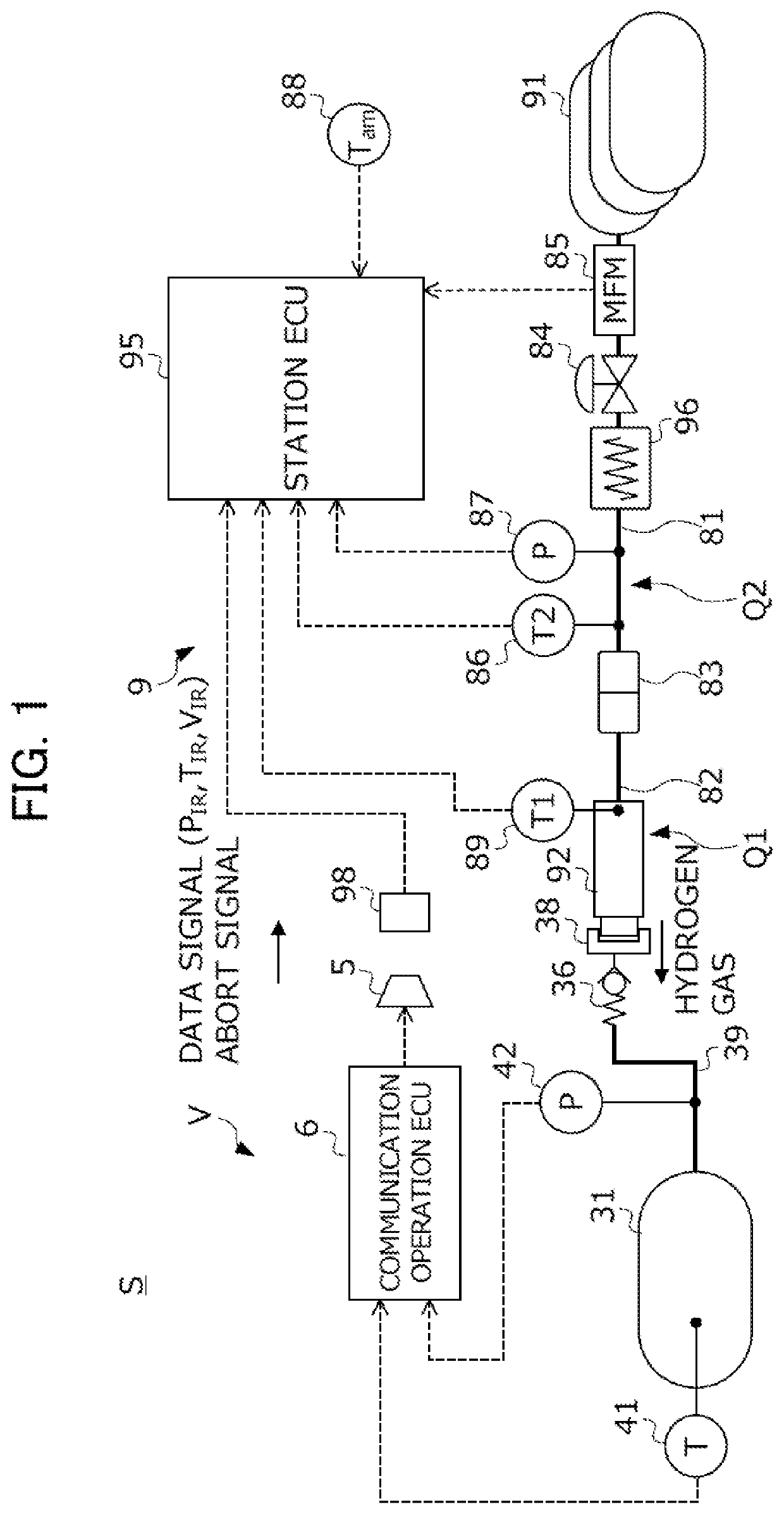
[0036]A first embodiment of the invention will now be described with reference to the accompanying drawings. FIG. 1 is a diagram illustrating a configuration of a hydrogen fueling system S based on a gas fueling method according to this embodiment. The hydrogen fueling system S is formed by combining a fuel cell vehicle V that travels by using a hydrogen gas as a fuel gas and a hydrogen station 9 that supplies the hydrogen gas to the hydrogen tank of the vehicle V. Hereinafter, first, a configuration of the vehicle V will be described. Subsequently, a configuration of the hydrogen station 9 will be described.

[0037]The vehicle V includes a hydrogen tank 31 that stores a hydrogen gas supplied from the hydrogen station 9, a vehicle pipe 39 extending from the hydrogen tank 31, a fuel cell system (not illustrated) that generates power using the hydrogen gas stored in the hydrogen tank 31 to drive the vehicle V using the generated power, an infrared (IR) communication unit 5 that transmit...

second embodiment

[0084]Next, a second embodiment of the invention will be described with reference to the accompanying drawings. A gas fueling method according to this embodiment is different from the gas fueling method of the first embodiment in the specific sequence of the initial fueling control. A specific configuration of the hydrogen fueling system for executing the gas fueling method according to this embodiment is similar to the hydrogen fueling system S of the first embodiment. Therefore, it will not be described repeatedly.

[0085]FIG. 6 is a flowchart illustrating a specific sequence of the initial fueling control according to this embodiment. In the initial fueling control of the first embodiment, the switching time tsw at which the initial fueling control is terminated and the main fueling control starts is set as a fixed value. In comparison, the initial fueling control according to this embodiment is different from the initial fueling control of the first embodiment in that the switchin...

third embodiment

[0092]Next, a third embodiment of the invention will be described with reference to the accompanying drawings. In the gas fueling method according to this embodiment, a specific sequence of the initial fueling control is different from that of the gas fueling method of the first embodiment. A specific configuration of the hydrogen fueling system for executing the gas fueling method according to this embodiment is similar to that of the hydrogen fueling system S of the first embodiment, and it will not be described repeatedly.

[0093]FIG. 8 is a flowchart illustrating a specific sequence of the initial fueling control according to this embodiment. In the initial fueling control of the first embodiment, there is only one chance to calculate the prediction value MAT_pred of the temperature parameter until the switching time tsw elapses from the start of the fueling. In comparison, the initial fueling control according to this embodiment is different from the initial fueling control of th...


PUM


Abstract

In order to provide a gas fueling method capable of suppressing overheating of a tank immediately after a start of fueling, in the gas fueling method, an accumulator and a hydrogen tank are coupled to each other with a gas flow passage. In a main fueling control at and after the timing t2, a sensor-based value MAT of a temperature parameter of a measurement position Q1 is calculated on the basis of a detection value of a first station temperature sensor, and the fueling control is performed on the basis of the sensor-based value MAT. In an initial fueling control at the timing t0 to t2, a prediction value MAT_pred of the temperature parameter is calculated at the timing t2 on the basis of an ambient temperature value, a mass flow rate value, and a heat capacity. The fueling control is performed on the basis of the prediction value MAT_pred.

Description

[0001]This application is based on and claims the benefit of priority from Japanese Patent Application No. 2017-224596, filed on 22 Nov. 2017, the content of which is incorporated herein by reference.BACKGROUND OF THE INVENTIONField of the Invention[0002]The present invention relates to a gas fueling method. More specifically, the present invention relates to a gas fueling method for coupling a gas supply source and a tank of a mobile object to each other with a gas flow passage provided with a cooling device and fueling the tank with the gas cooled by the cooling device.Related Art[0003]A fuel cell vehicle travels by supplying an oxygen containing air and a hydrogen gas as a fuel gas to a fuel cell and driving an electric motor using power generated thereby. In recent years, practical application of fuel cell vehicles using such a fuel cell as an energy source for generating power has been progressed. While the hydrogen gas is necessary to generate power using the fuel cell, in rec...

Claims


Application Information

Patent Timeline
Patent Type & Authority Patents(United States)
IPC IPC(8): F02M53/04G05D7/06F02M21/02B60L50/70
CPCF02M53/04B60L50/70F02M21/0206G05D7/0635H01M2250/20B60L2240/662B60L2260/56B60L58/33Y02T90/16Y02E60/32Y02T10/72Y02T90/40Y02E60/50
Inventor HANDA, KIYOSHI
Owner HONDA MOTOR CO LTD
Why Eureka
Try Eureka