Exhaust gas control system

a control system and exhaust gas technology, applied in the direction of engines, mechanical equipment, machines/engines, etc., can solve the problems of urea aqueous solution deterioration, unsatisfactory situations, and deterioration of on-vehicle mountability, so as to suppress the overheating of the urea addition valve and prevent the cooling efficiency

Active Publication Date: 2019-03-19
TOYOTA JIDOSHA KK
View PDF7 Cites 0 Cited by
  • Summary
  • Abstract
  • Description
  • Claims
  • Application Information

AI Technical Summary

Benefits of technology

[0008]The present disclosure provides a technology for an exhaust gas control system including a fuel addition valve and a urea addition valve, the technology being capable of suppressing overheating of the urea addition valve while cooling the fuel addition valve.
[0022]The present disclosure can suppress overheating of the urea addition valve while cooling the fuel addition valve.

Problems solved by technology

This may induce undesirable situations such as operation failure of the fuel addition valve or the urea addition valve.
The method, however, involves complicated piping of the refrigerant, which causes a problem of deteriorated on-vehicle mountability.
However, urea aqueous solution tends to deteriorate at temperature lower than fuel, and therefore when the fuel addition valve is cooled in preference to the urea addition valve, the urea aqueous solution stagnating around the nozzle hole of the urea addition valve is overheated to the urea aqueous solution deterioration temperature.
This may induce operation failure of the urea addition valve.

Method used


Image

  • Exhaust gas control system
  • Exhaust gas control system
  • Exhaust gas control system

Examples


first embodiment

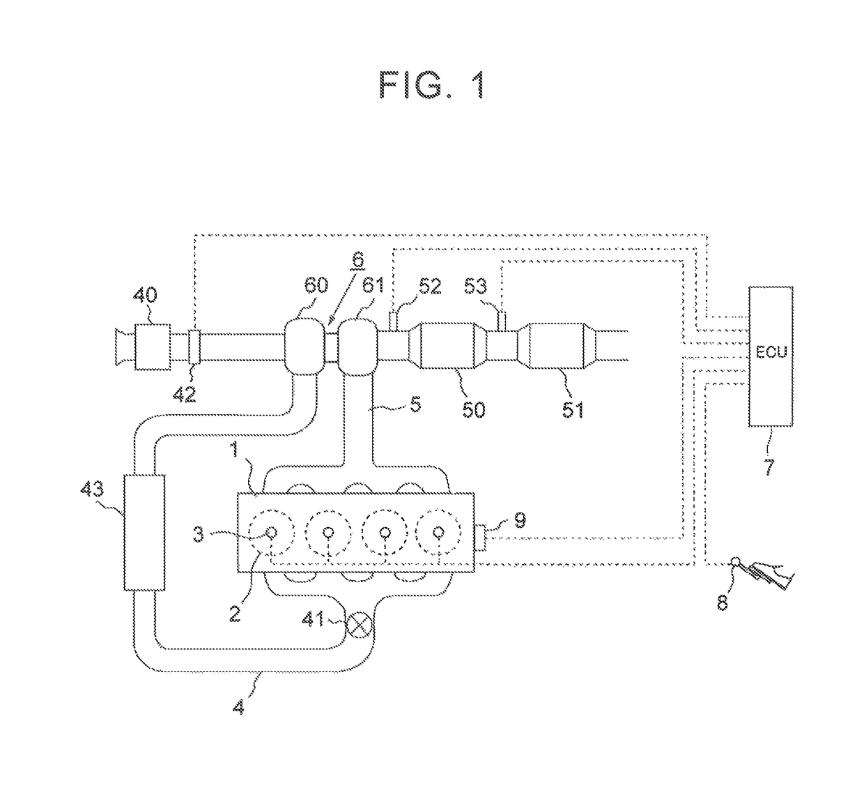
[0036]First, the present disclosure will be described with reference to FIGS. 1 through 4. FIG. 1 illustrates a schematic configuration of an internal combustion engine according to the present embodiment. The internal combustion engine 1 illustrated in FIG. 1 is a compression ignition type internal combustion engine (diesel engine) operated at an air-fuel ratio leaner than a theoretical air fuel ratio. In the example illustrated in FIG. 1, the internal combustion engine 1 has four cylinders 2 disposed in series. However, the internal combustion engine 1 may have three cylinders 2 or less, or may have five cylinders 2 or more. The cylinders 2 of the internal combustion engine 1 are each equipped with a fuel injection valve 3 that injects fuel into the cylinder 2.

[0037]The internal combustion engine 1 is connected to an intake passage 4. The intake passage 4 is a passage for guiding the air, which is taken in from the atmosphere, to each of the cylinders 2. In the vicinity of an upst...

second embodiment

[0070]In the second embodiment described before, the exhaust gas control system is divided into two systems. However, in the present modification, part of the exhaust gas control system is divided into two systems.

[0071]FIG. 9 illustrates a schematic configuration of an internal combustion engine and an exhaust system thereof in the present modification. In FIG. 9, component members similar to those in the second embodiment described before are designated by similar reference signs. The exhaust system of the internal combustion engine 1 illustrated in FIG. 9 includes a first exhaust passage 5a′ connected to the first bank 100a, a second exhaust passage 5b′ connected to the second bank 100b, and a third exhaust passage 5c formed by confluence of the first exhaust passage 5a′ and the second exhaust passage 5b′ (a position at which the first exhaust passage 5a′ and the second exhaust passage 5b′ converge with each other). In the course of the first exhaust passage 5a′, a turbine 61a of...


PUM


Abstract

A first fuel addition valve disposed in a portion of a first exhaust passage upstream from a first upstream purification device, a first urea addition valve disposed in a portion of the first exhaust passage between the first upstream purification device and a first downstream purification device, and a first valve cooling passage configured such that i) refrigerant passes the first urea addition valve and the first fuel addition valve in order, and ii) the refrigerant cools the first fuel addition valve after the refrigerant cools the first urea addition valve.

Description

INCORPORATION BY REFERENCE[0001]The disclosure of Japanese Patent Application No. 2016-129884 filed on Jun. 30, 2016 including the specification, drawings and abstract is incorporated herein by reference in its entirety.BACKGROUND[0002]1. Technical Field[0003]The present disclosure relates to an exhaust gas control system for an internal combustion engine.[0004]2. Description of Related Art[0005]A system known as an exhaust gas control system for an internal combustion engine includes: an oxidation catalyst disposed in an exhaust passage of the internal combustion engine; a selective catalytic; reduction (SCR) catalyst disposed in a portion of the exhaust passage downstream from the oxidation catalyst; a fuel addition valve disposed in a portion of the exhaust passage upstream from the oxidation catalyst, the fuel addition valve being configured to add fuel to the exhaust gas; and a urea addition valve disposed in a portion of the exhaust passage between the fuel addition valve and ...

Claims


Application Information

Patent Timeline
Patent Type & Authority Patents(United States)
IPC IPC(8): F01N3/00F01N3/20F01N3/025F01N3/04F01P3/20
CPCF01N3/043F01N3/0253F01N3/2033F01P3/20F01N3/2066F01P2060/12F01N2610/02F01N2610/1453Y02T10/12
Inventor ASAURA, SHINYASATO, MASAAKIONO, RYOHEIMIYOSHI, YUJI
Owner TOYOTA JIDOSHA KK
Why Eureka
Try Eureka