Apparatus for optically reading information stored in graphic symbol

a technology of graphic symbols and apparatuses, applied in the direction of optical elements, instruments, electromagnetic radiation sensing, etc., can solve the problems of deteriorating the efficiency of reading difficult to properly read and affecting the reading efficiency of the information stored in the information symbol

Inactive Publication Date: 2014-08-12
DENSO WAVE INC
View PDF32 Cites 3 Cited by
  • Summary
  • Abstract
  • Description
  • Claims
  • Application Information

AI Technical Summary

Problems solved by technology

This may cause improper reading of the information stored in the information symbol
Particularly, in reading an information symbol directly marked on a metal surface of goods in direct marking, such specular reflection may likely appear, making it difficult to properly read the information stored in the information symbol.
This may deteriorate the efficiency of reading the information stored in the information symbol.
However, in the optical information reader of the second example, the structure of the mechanical change of the incident angle may increase in complexity.
However, in the image reader of the third example, because the image superimposing task is carried out pixel by pixel of each of the first and second images of the target, it may increase in complexity.
However, the narrower the angle of view of an imaging lens is, the narrower the field of view of a photodetector is.
However, it may be difficult for an information reader with an imaging unit having a narrow angle of view to pick up an image of an information symbol consisting of a plurality of comparatively large-sized unit sections of information.

Method used


Image

  • Apparatus for optically reading information stored in graphic symbol
  • Apparatus for optically reading information stored in graphic symbol
  • Apparatus for optically reading information stored in graphic symbol

Examples


first embodiment

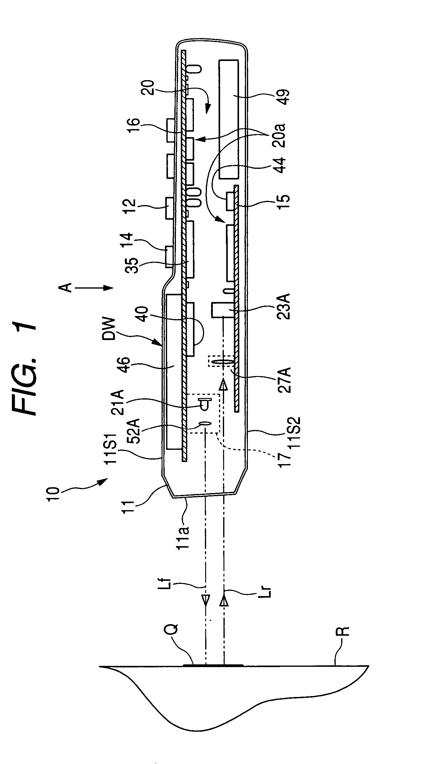
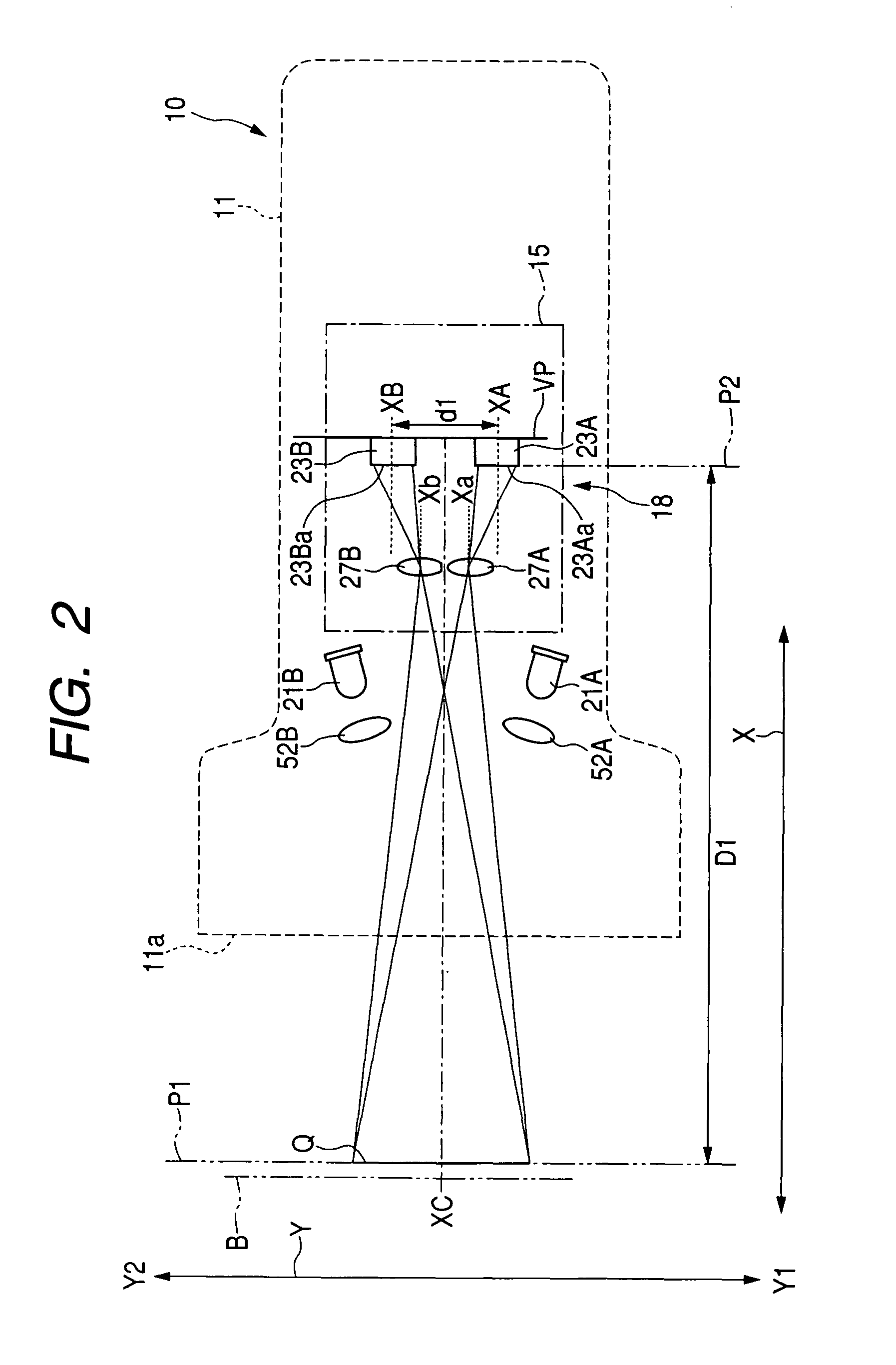
[0077]Referring to FIGS. 1 to 3, an optical information reader 10 according to a first embodiment of the present invention, referred to simply as “information reader 10”, is designed to read graphic symbols including two-dimensional codes, such as QR codes, barcodes, or other various types of graphic symbols.

[0078]The graphic symbols have been attached to targets, such as commercial goods or the like, by directly or indirectly marking, printing, or using other methods. The target R includes a label that is a piece of paper or another media. The target R can be attached on goods, which is the same as general barcodes. For example, such a graphic symbol includes information, such as a manufacturer serial number, a name, a unique identification number, a date of manufacture of the corresponding target, and the like.

[0079]In recent years, the screen of a display (e.g. a liquid crystal display) in computer terminals including a cellular phone, a PDA (Personal Digital Assistant), or the l...

second embodiment

[0238]Referring to FIGS. 11 and 12, a barcode reader 110 as an example of optical information readers according to a second embodiment of the present invention is designed to read graphic symbols including barcodes.

[0239]The barcode reader 110 is provided with a substantially gun-shaped housing (case) 111, a reading unit 114, and a data processing unit 116.

[0240]The case 111 consists of an upper case part 111U and a lower case part 111L. The upper case part 111U has an elongated hollow box structure with one opening surface, and the lower case part 111L has the symmetrical structure as the upper case part 111U. The case 111 is assembled such that the upper case part 111U is mounted at its opening-surface side edge on the opening-surface side edge of the lower case part 111L.

[0241]One end portion H of the case 111 in its longitudinal direction is bent to be directed diagonally to the longitudinal direction. The bent portion H of the case 111 will be referred to as “head portion H” he...

third embodiment

[0307]An optical information reader according to a third embodiment of the present invention will be described hereinafter. The structure of the optical information reader according to the third embodiment is substantially identical to that of the optical information reader 10 according to the first embodiment.

[0308]Thus, like reference characters are assigned to like parts in the optical information readers according to the first and third embodiments, and therefore, descriptions of the structure of the optical information reader according to the third embodiment are omitted.

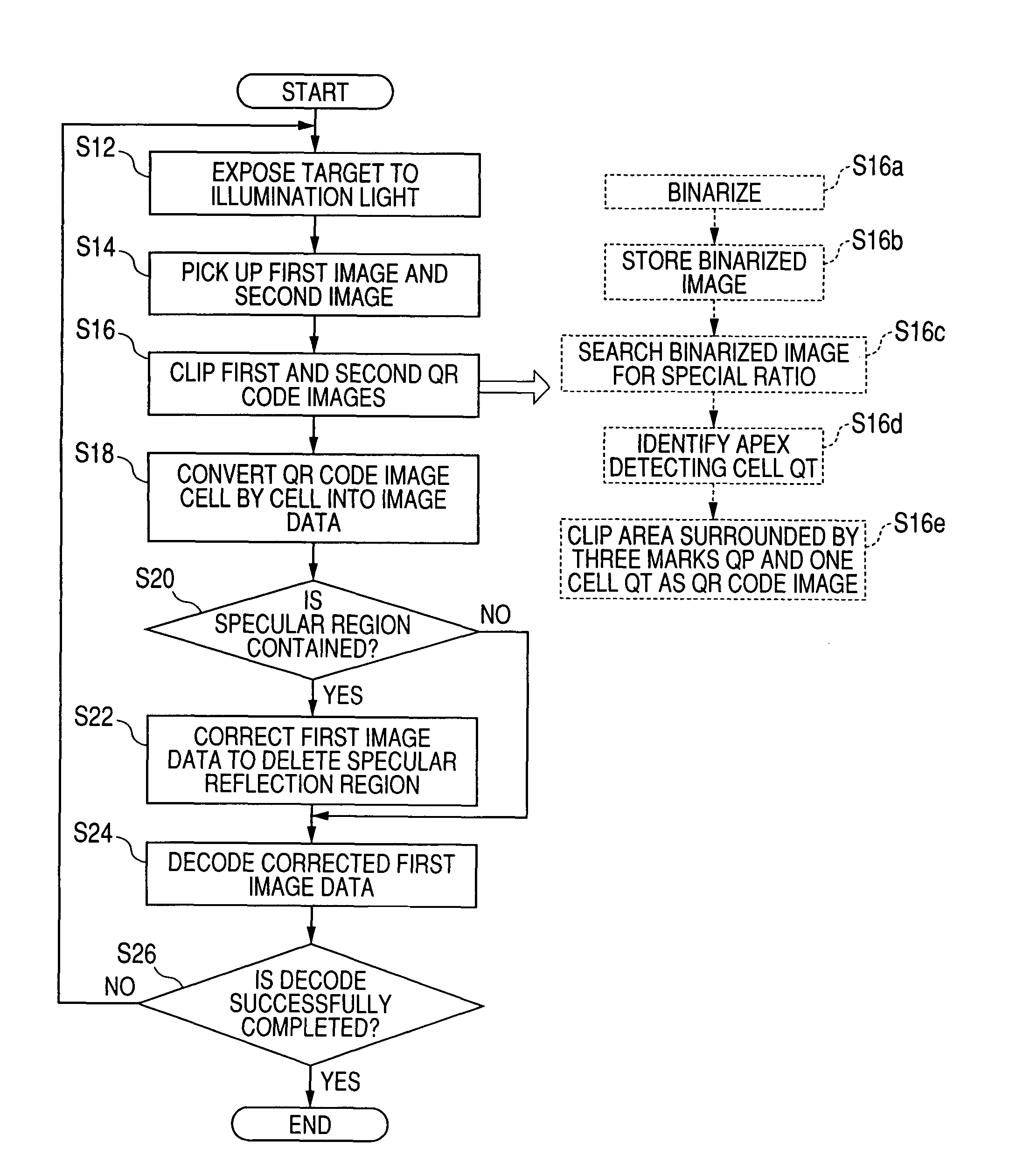
[0309]Operations of the information reader 10 according to the third embodiment, which are different from those of the reader according to the first embodiment, will be described hereinafter with reference to FIGS. 14 to 17 hereinafter.

[0310]In the information reader 10 according to the third embodiment, the tasks in steps S112 and S114 of FIG. 14, which are identical to those in steps S12 and S14 of FIG. 6, ar...


PUM


Abstract

In an apparatus for optically reading a graphic symbol composed of a plurality of optically identifiable unit sections of information, a first image pickup unit has a first photodetector and picks up a first optical image of the graphic symbol based on light detected by the first photodetector. A second image pickup unit has a second photodetector and configured to pick up a second optical image of the graphic symbol based on light detected by the second photodetector. A correcting unit corrects a light intensity level of at least one section of one of the first and second optical images based on a light intensity level of at least one section of the other of the first and second optical images. The at least one section corresponds to at least one of the unit sections of information of the graphic symbol.

Description

CROSS REFERENCE TO RELATED APPLICATIONS[0001]This application is based on Japanese Patent Applications 2006-172957, 2006-241504, and 2007-075345 which were respectively filed on Jun. 22, 2006, Sep. 6, 2006, and Mar. 22, 2007. This application aims the benefit of priority from the Japanese Patent Applications, so that the descriptions of which are all incorporated herein by reference.FIELD OF THE INVENTION[0002]The present invention relates to apparatuses capable of optically reading graphic symbols, such as barcodes, QR Codes®, and the like, used to be attached to targets, such as commercial goods.BACKGROUND OF THE INVENTION[0003]Optical information readers that aim at optically reading information symbols, such as barcodes, QR codes, and the like, attached to goods and documents have been well known.[0004]Such optical information readers are each made up of a handheld body case provided at its one end portion with a reading window; a photodetector, such as a CCD (Charge-Coupled Dev...

Claims


Application Information

Patent Timeline
Patent Type & Authority Patents(United States)
IPC IPC(8): G06K7/10G06K5/04G06K7/14G06K9/00G06K9/22G06K9/36G06K9/80G06K19/06G06K19/08G06K21/00G06V30/224
CPCG06K7/10722G06K7/1417G06K7/1473G06K7/10G06K7/00
Inventor TANAKA, MASAMIITO, KUNIHIKOMIYAZAKI, MANABUOTA, HIROSHIKONOSU, KOJI
Owner DENSO WAVE INC
Why Eureka
Try Eureka