Contact switches in a uniform control panel

a technology of contact switches and control panels, applied in the directions of legends, transportation and packaging, and dashboard fitting arrangements, can solve problems such as not optimum solutions, and achieve the effect of convenient visual recognition and cost-effectiveness

Inactive Publication Date: 2014-08-12
TRW AUTOMOTIVE ELECTRONICS & COMPONENTS GMBH & CO KG
View PDF15 Cites 0 Cited by
  • Summary
  • Abstract
  • Description
  • Claims
  • Application Information

AI Technical Summary

Benefits of technology

[0005]The pushbutton switch array according to the invention has a frame which is covered by a transparent film and includes recesses which selectively have an actuating element accommodated therein for displacement or a dummy element accommodated therein so as to be non-displaceable. The actuating elements are provided with symbols on the surface thereof facing the film and hold a printed circuit board at the opposite end. The printed circuit board carries a switch element that cooperates with a contact element on an opposite base plate. The transparent film, which completely covers the frame along with the actuating elements and the dummy elements, provides a continuous smooth surface. Arranged behind the film are the actuating elements, which are identifiable only by the selectively illuminated symbols. Depending on the switching state, the illumination of the symbols may be different, so that the respective switching state can be easily recognized visually. The switching functions are each implemented by an actuating element in cooperation with the switch element on the printed circuit board and the contact element on the base plate. In comparison with the equipment with autonomous switch units, this is a very cost-effective solution.

Problems solved by technology

This is a flexible, though not optimum solution because the recesses closed by a dummy cover are both visible and tactile.

Method used


Image

  • Contact switches in a uniform control panel
  • Contact switches in a uniform control panel

Examples


Embodiment Construction

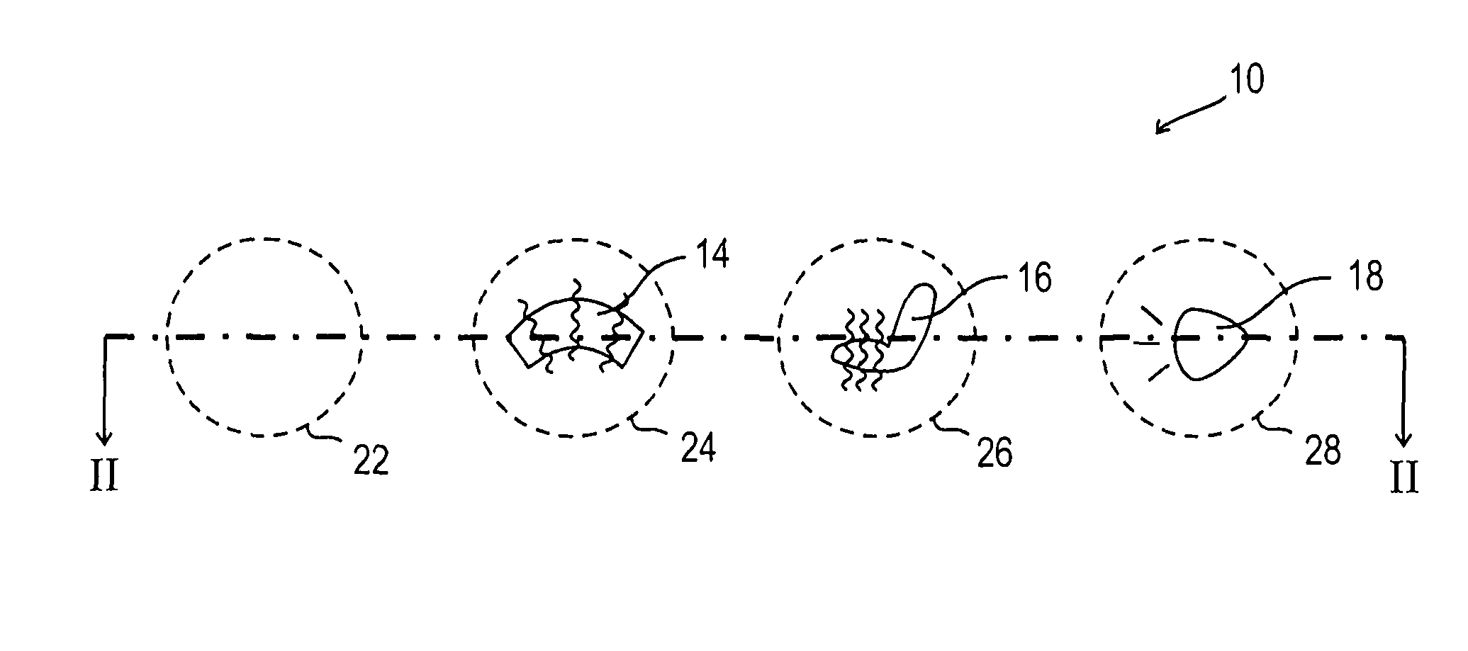
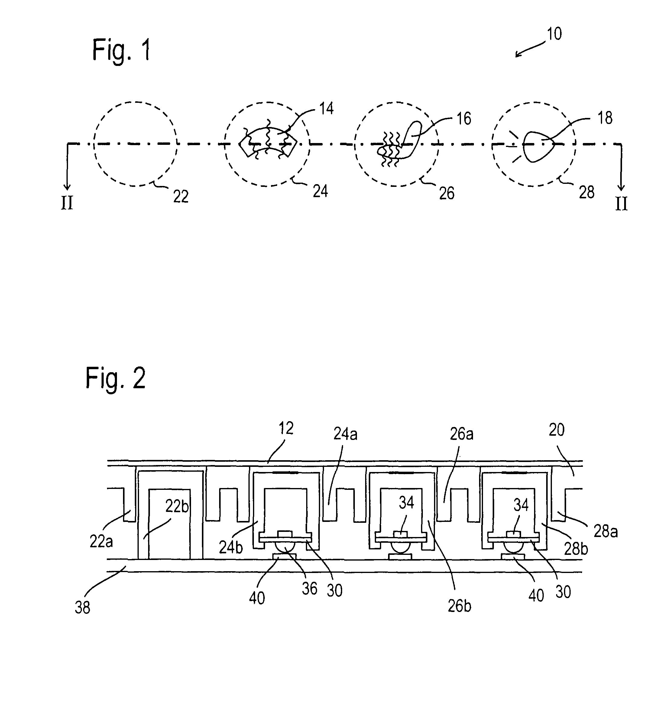
[0010]FIG. 1 shows a smooth operating panel 10 which is formed by a transparent film 12 (FIG. 2). Three symbols 14, 16, 18 shown by way of example are visible through the film. Round recesses 22, 24, 26, 28 formed in a frame 20 (FIG. 2) under the film are indicated in dashed lines. The recess 22 is not equipped with a switch unit; therefore, no symbol can be seen.

[0011]The frame 20 is formed by a plastic support made from an opaque material. The frame has the round recesses 22 to 28 indicated in FIG. 1, which are defined by cylindrical walls 22a, 24a, 26a and 28a. The wails 24a to 28a constitute sliding guides for inserted cap-shaped actuating elements 24b, 26b, 28b, whereas the wall 22a receives a likewise cap-shaped dummy element 22b which is not displaceable.

[0012]On their surfaces facing the film 12, the actuating elements 24b, 26b and 28b are provided with the symbols 14, 16 and 18. The symbols may be printed on the respective surface if the latter is formed by a light-transmis...


PUM


Abstract

A pushbutton switch array is proposed which provides a uniform operating surface in which switching units are distinguished from dummy elements only by symbols provided on the switching units and the switching units are realized with few functional parts. The pushbutton switch array has a frame which is covered by a transparent film and includes recesses which selectively have an actuating element accommodated therein for displacement or a dummy element accommodated therein so as to be non-displaceable. The actuating elements are provided with symbols on the surface thereof facing the film and hold a printed circuit board at the opposite end. The printed circuit board carries a switch element that cooperates with a contact element on an opposite base plate. The transparent film, which completely covers the frame along with the actuating elements and the dummy elements, provides a continuous smooth surface. Arranged behind the film are the actuating elements, which are identifiable only by the selectively illuminated symbols.

Description

RELATED APPLICATIONS[0001]This application corresponds to PCT / EP2010 / 004236, filed, which claims the benefit of German Application No. 10 2009 036 212.6, filed Aug. 5, 2009, the subject matter, of which is incorporated herein by reference in its entirety.BACKGROUND OF THE INVENTION[0002]The present invention relates to a pushbutton switch array which is specially suited for use as an operating panel in a motor vehicle.[0003]Switch arrays that are built into a uniform faceplate are generally known. The faceplate has recesses arranged in a fixed grid, with a complete switch unit or else a dummy cover being inserted in the recesses as required. This is a flexible, though not optimum solution because the recesses closed by a dummy cover are both visible and tactile. Also, it is an involved solution because the switch units used are configured to be completely autonomous with all required functional parts inclusive of the housing.SUMMARY OF THE INVENTION[0004]The invention provides a pus...

Claims


Application Information

Patent Timeline
Patent Type & Authority Patents(United States)
IPC IPC(8): H01H9/00
CPCH01H2223/002H01H2221/026H01H2215/036H01H13/83H01H2205/002H01H2217/022B60K2350/2039H01H2221/07H01H2217/018B60K37/06H01H2219/028B60K2370/34
Inventor KORHERR, JOACHIMKOEHNLEIN, HARALD
Owner TRW AUTOMOTIVE ELECTRONICS & COMPONENTS GMBH & CO KG
Why Eureka
Try Eureka