Photoacoustic image-generating apparatus and light source control method

a technology of photoacoustic image and light source, which is applied in the field of photoacoustic image generation apparatus, can solve the problems of insufficient intensity of photoacoustic wave due to light irradiation from the tip of the needle, difficulty in recognizing the position of the puncture needle in the photoacoustic image, etc., and achieves the suppression of flare-like artifacts, the effect of increasing the amount of light emitted from the light source and decreasing

Active Publication Date: 2019-03-26
FUJIFILM CORP
View PDF11 Cites 1 Cited by
  • Summary
  • Abstract
  • Description
  • Claims
  • Application Information

AI Technical Summary

Benefits of technology

[0009]For the above-described problem, it is considered that light is guided to the tip of the needle and light irradiation is performed from the tip of the needle. Since the light is guided to the tip of the needle, the light can be irradiated at the tip of the needle even if the tip of the needle is punctured in the subject deeply. For this reason, even if the tip of the needle is punctured to a deep position, compared to the case where light irradiation is performed from the surface of the subject, a photoacoustic wave can be generated. Furthermore, since a photoacoustic wave can be selectively generated at the portion of the tip of the needle, the tip of the needle is easily recognized visually.
[0011]An object of the invention is to provide a photoacoustic image-generating apparatus and a light source control method capable of improving visibility of a tip portion of an inserted object when light is guided to the tip portion of the inserted object to generate a photoacoustic wave and the tip portion of the inserted object is visualized using a photoacoustic image in consideration of the above description.
[0025]The light source control unit may control the amount of light emitted from the light emission unit to the amount of light within a range of a maximum permissible exposure to the subject in the case where the photoacoustic wave from the inserted object is not detected. The “maximum permissible exposure” refers to “the level of laser irradiation without giving harmful effects on a human body even if the human body is irradiated with laser in a normal environment” based on a method defined in the safety standards (JIS C 6802) of laser products.
[0029]In the photoacoustic image-generating apparatus and the light source control method of the invention, light from the light source is guided to the inserted object to generate the photoacoustic wave in the tip portion, the photoacoustic image in which the photoacoustic wave is detected is generated, and the amount of light irradiating the tip portion of the inserted object is controlled based on the photoacoustic image. For example, in the case where the detected photoacoustic wave is weak, the amount of light emitted from the light source is increased, whereby the photoacoustic wave generated in the tip portion of the inserted object is intensified. Conversely, in the case where the detected photoacoustic wave is intense, the amount of light emitted from the light source is decreased, whereby the photoacoustic wave generated in the tip portion of the inserted object is weakened. In this way, even if the inserted object is inserted to a deep position of the subject, the position of the tip of the inserted object can be confirmed using the photoacoustic image. Furthermore, it is possible to suppress the occurrence of a flare-like artifact in the case where the insertion position of the inserted object is shallow, or the occurrence of an artifact due to multiple reflections, and to improve visibility of the tip portion of the inserted object

Problems solved by technology

In particular, if the tip of the puncture needle is punctured to a deep position, light irradiated from the surface of the subject does not sufficiently reach the puncture needle which has been punctured to the deep position, and it is difficult to recognize the position of the puncture needle in the photoacoustic image.
Furthermore, since light is irradiated from the outside of the needle, a photoacoustic wave is generated from the entire needle body as well as from the tip, and the tip of the needle is hardly recognized visually.
However, in the case that the light is guided to the tip of the needle, if the intensity of the light irradiated from the tip of the needle is too weak when the tip of the needle is punctured in the subject deeply, a photoacoustic wave due to light irradiation from the tip of the needle cannot be detected to the sufficient intensity, and the tip of the needle is not easily recognized in a photoacoustic image.
On the other hand, if the intense light is irradiated from the tip of the needle while the tip of the needle is punctured in the subject deeply, an intense photoacoustic wave is detected when the tip of the needle is punctured to a shallow position, causing a flare-like artifact or an artifact due to multiple reflections, and visibility of the tip of the needle is degraded.
This problem occurs not only when using the puncture needle, but also when the position of the tip of the inserted object which is inserted into the subject is recognized using a photoacoustic image.

Method used


Image

  • Photoacoustic image-generating apparatus and light source control method
  • Photoacoustic image-generating apparatus and light source control method
  • Photoacoustic image-generating apparatus and light source control method

Examples


Embodiment Construction

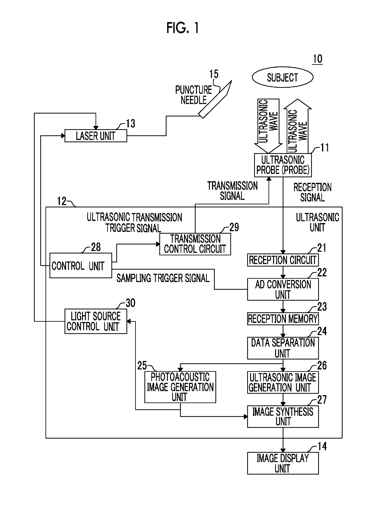
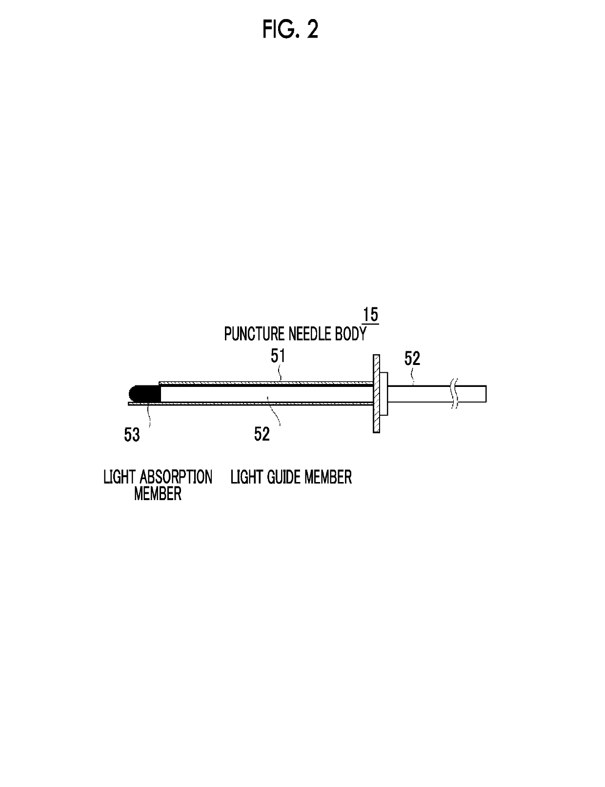
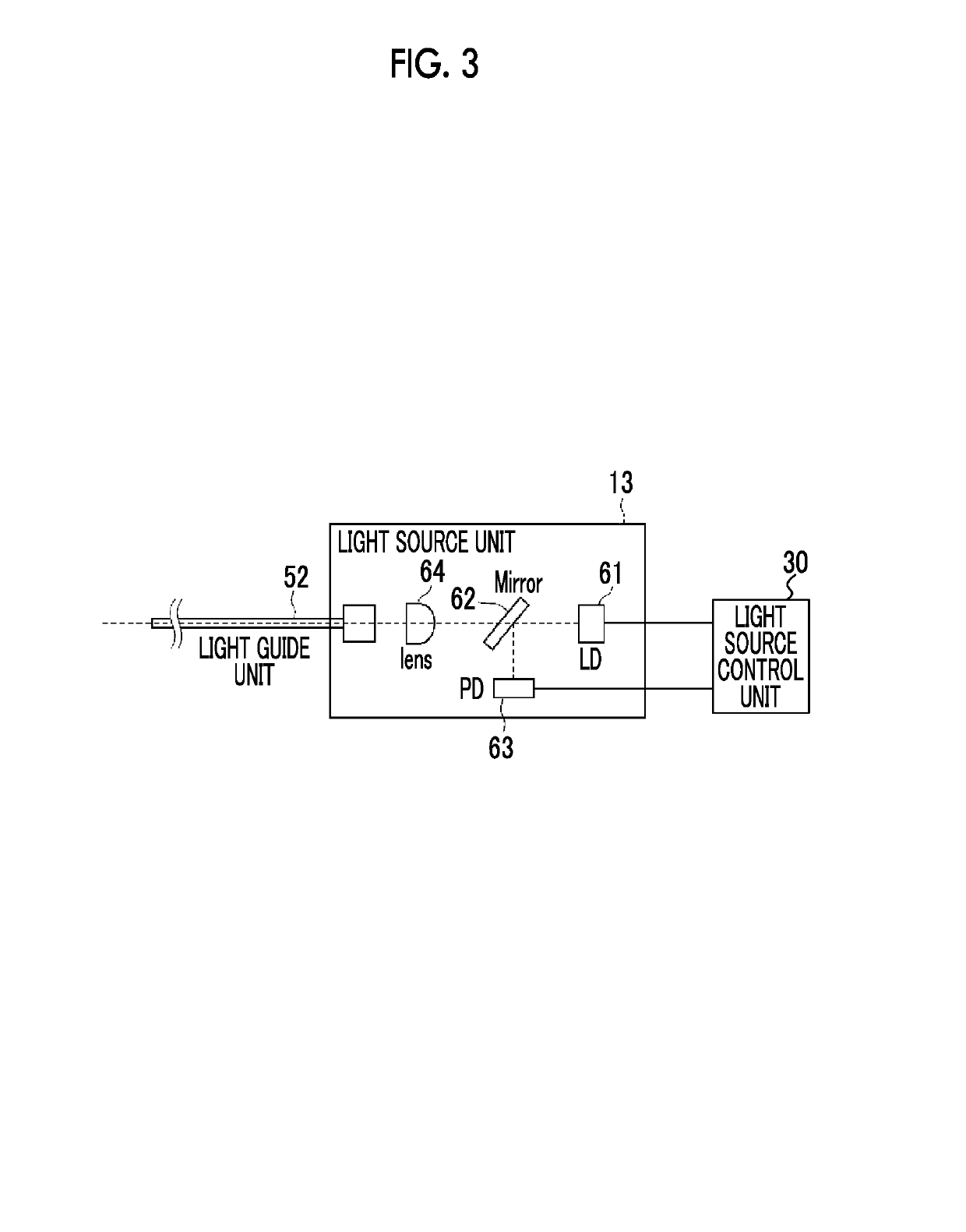
[0039]Hereinafter, an embodiment of the invention will be described in detail referring to the drawings. FIG. 1 shows a photoacoustic image-generating apparatus according to an embodiment of the invention. A photoacoustic image-generating apparatus (photoacoustic image diagnostic apparatus) 10 includes a probe (ultrasonic probe) 11, an ultrasonic unit 12, and a laser unit 13. In the embodiment of the invention, although an ultrasonic wave is used as an acoustic wave, the acoustic wave is not limited to the ultrasonic wave, and an acoustic wave of an audio frequency may be used as long as an appropriate frequency is selected according to an inspection target, measurement conditions, or the like.

[0040]The laser unit 13 is a light source which emits light guided to an inserted object, and includes, for example, a laser diode (semiconductor laser). The type of the laser is not particularly limited, and may be, for example, a solid-state laser using yttrium aluminum garnet (YAG), alexand...


PUM


Abstract

At least a tip portion of a puncture needle 15 is inserted into a subject. The puncture needle 15 includes a light guide member which guides light from a laser unit 13, and a light emission unit which is provided in the vicinity of the tip portion and emits light guided by the light guide member, and generates a photoacoustic wave caused by light from the light emission unit in the tip portion. A probe 11 detects the photoacoustic wave from the puncture needle 15 in a state where the puncture needle 15 is inserted into the subject. A Photoacoustic image generation unit 25 generates a photoacoustic image based on the detected photoacoustic wave. A Light source control unit 30 controls the amount of light emitted from the light emission unit based on the photoacoustic image.

Description

CROSS-REFERENCE TO RELATED APPLICATIONS[0001]This application is a Continuation of PCT International Application No. PCT / JP2014 / 065954 filed on Jun. 17, 2014, which claims priority under 35 U.S.C § 119 (a) to Japanese Patent Application No. 2013-161232 filed on Aug. 2, 2013 and Japanese Patent Application No. 2014-117396 filed on Jun. 6, 2014. Each of the above application(s) is hereby expressly incorporated by reference, in its entirety, into the present application.BACKGROUND OF THE INVENTION[0002]1. Field of the Invention[0003]The present invention relates to a photoacoustic image-generating apparatus which generates a photoacoustic image based on a photoacoustic wave caused by light irradiation. Also, the present invention relates to a method of controlling a light source in the photoacoustic image-generating apparatus.[0004]2. Description of the Related Art[0005]As a kind of an image inspection method capable of noninvasively inspecting the internal state of a living body, an u...

Claims


Application Information

Patent Timeline
Patent Type & Authority Patents(United States)
IPC IPC(8): A61B5/00A61B8/00A61B8/08
CPCA61B5/0095A61B5/0035A61B8/4416A61B5/6848A61B2576/00A61B8/0841A61B5/061
Inventor MURAKOSHI, DAI
Owner FUJIFILM CORP
Why Eureka
Try Eureka