Balanced turbine rotor fan blade for a tip turbine engine

a tip turbine engine and fan blade technology, which is applied in the field of hollow fan blades, can solve the problems of complicated or prevent engine packaging, excessive bending stresses, etc., and achieve the effect of minimizing the moment, minimizing the radial space required for airflow discharge, and minimizing unacceptable bending stresses and deflections

Inactive Publication Date: 2014-08-19
UNITED TECH CORP
View PDF149 Cites 0 Cited by
  • Summary
  • Abstract
  • Description
  • Claims
  • Application Information

AI Technical Summary

Benefits of technology

[0010]The airflow through the core airflow passage is turned to flow relatively axially by the diffuser section. The core airflow is turned, spread and split into two airflow streams which are ducted toward opposite ends of the diffuser section by a multiple of internal turning vanes. The airflow streams are then further turned by discharge turning vanes before discharge from the diffuser discharge outlet. The flow areas of each adjacent airflow stream are open such that the internal pressure of each adjacent airflow stream will interact with the others allowing flows and pressures to equalize and ensure consistent discharge.
[0011]As the core airflow is turned, the aspect ratio of the core airflow is oriented to discharge through an annulus defined by a multitude of diffuser discharge outlets. The diffuser section is positioned relative the fan blade airfoil section so as to locate the diffuser center of mass to minimize the moment on the hollow fan blade segment generated by the rotational force of the annular diffuser. These features result in a “whale tail” diffuser section shape. The diffuser section of each “whale tail” fan blade nests into the shape of the adjacent fan blades to form the complete annular diffuser which maximizes the available diffuser flow area formed from each diffuser discharge outlet such that the radial space required for airflow discharge is minimized.
[0012]Along with turning and splitting the core airflow, the fan blade profile of the present invention balances the mass of the diffuser section such that the center of mass thereof is over the hollow fan blade airfoil section structure. Any annular structure mounted about the annular diffuser such as tip turbine blade segments mounted on the outer periphery of the diffuser sections will likewise be so balanced. Centrifugal forces on the diffuser section create only tensile stresses in the hollow fan blade airfoil section which minimizes unacceptable bending stresses and deflections.
[0013]The present invention therefore provides a lightweight hollow fan blade with a core airflow passage which turns an airflow within a minimal radial turning distance without excessive losses while assuring a balanced tip shroud mass.

Problems solved by technology

This elongated shape may complicate or prevent packaging of the engine into particular applications.
Communicating airflow through the hollow fan blades within a relatively limited radial turning distance of a fan turbine rotor without excessive losses provides an engine design challenge.
During rotational loading, the mass imbalance about the fan blade outer periphery may generate a moment on the fan blade leading to excessive bending stresses.

Method used


Image

  • Balanced turbine rotor fan blade for a tip turbine engine
  • Balanced turbine rotor fan blade for a tip turbine engine
  • Balanced turbine rotor fan blade for a tip turbine engine

Examples


Embodiment Construction

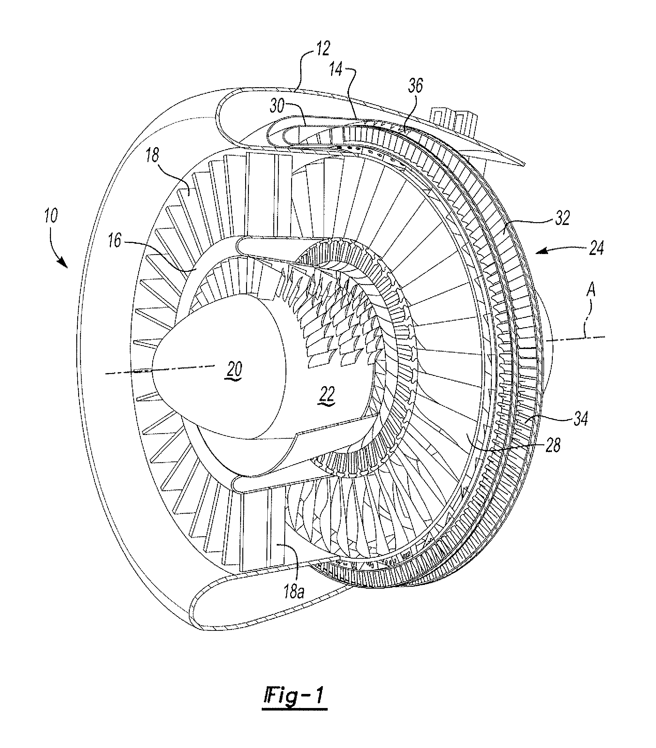
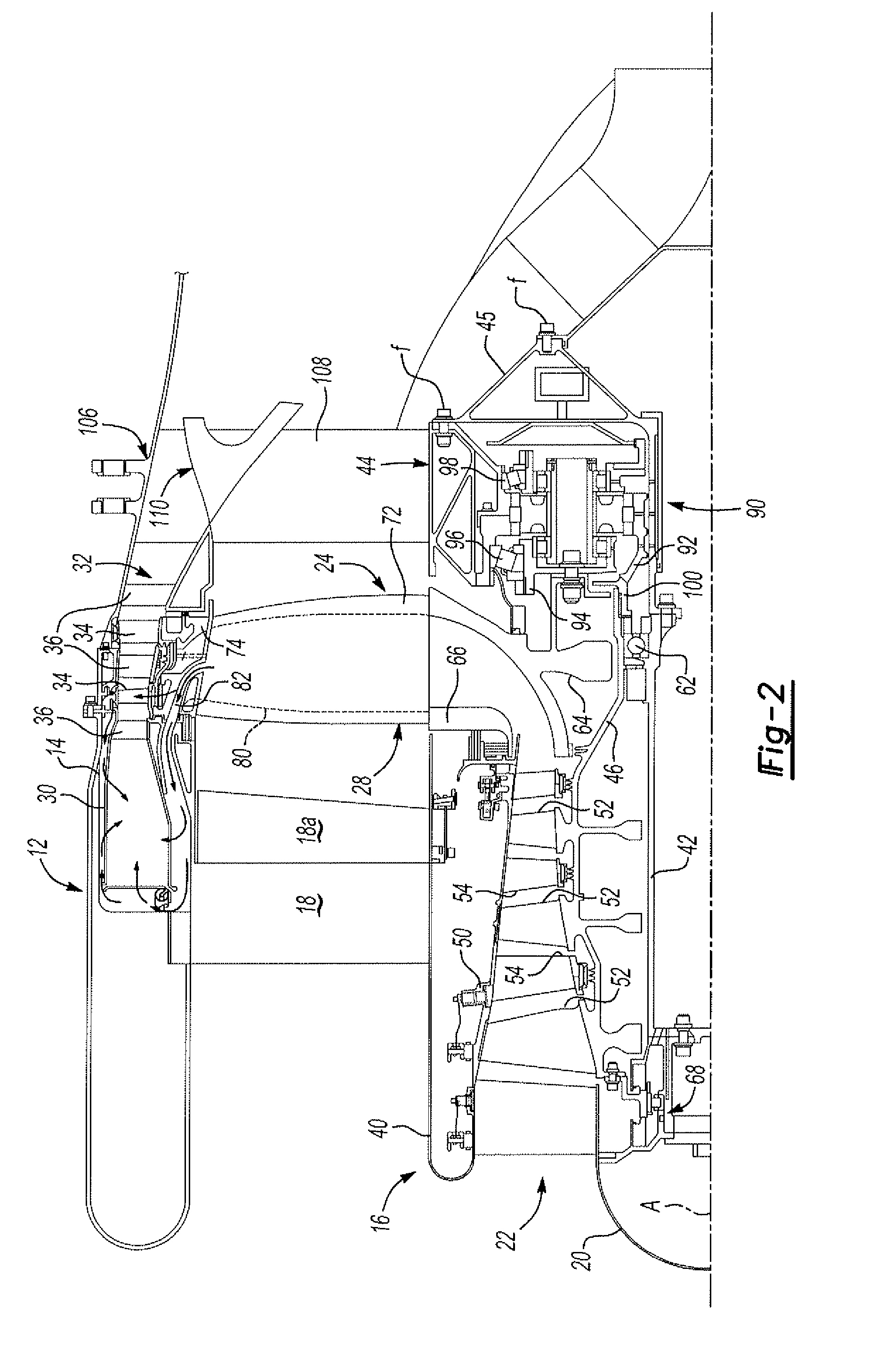
[0024]FIG. 1 illustrates a general perspective partial sectional view of a tip turbine engine type gas turbine engine 10. The engine 10 includes an outer nacelle 12, a rotationally fixed static outer support structure 14 and a rotationally fixed static inner support structure 16. A multitude of fan inlet guide vanes 18 are mounted between the static outer support structure 14 and the static inner support structure 16. Each inlet guide vane 18 preferably includes a movable trailing edge portion 18A which may be articulated relative to the fixed inlet guide vane 18.

[0025]A nose cone 20 is preferably located along the engine centerline A to smoothly direct airflow into an axial compressor 22 adjacent thereto. The axial compressor 22 is mounted about the engine centerline A behind the nose cone 20.

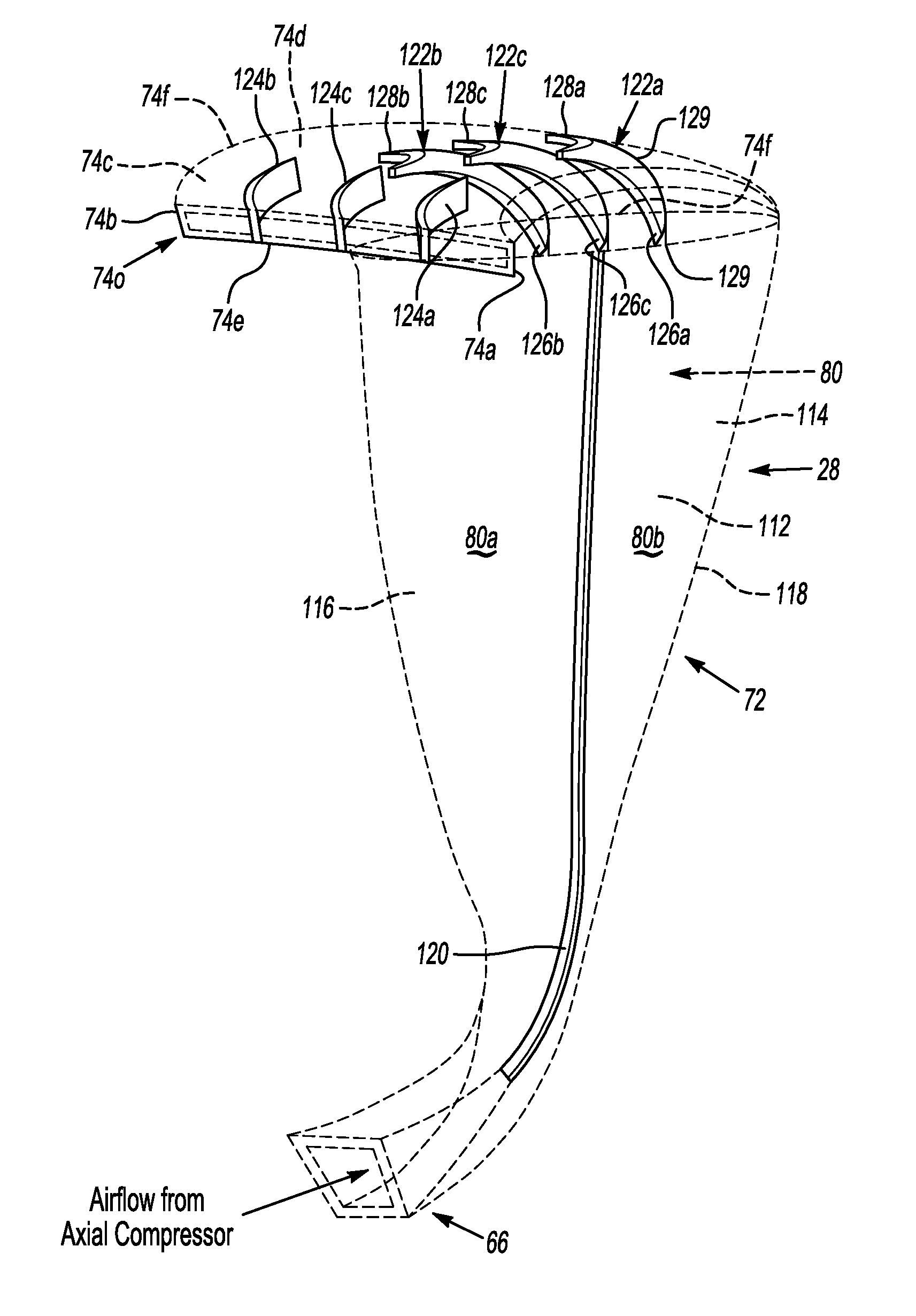
[0026]A fan-turbine rotor assembly 24 is mounted for rotation about the engine centerline A aft of the axial compressor 22. The fan-turbine rotor assembly 24 includes a multitude of hollow fan...


PUM


Abstract

A fan-turbine rotor assembly for a tip turbine engine includes a multiple of fan blades, which include an inducer section, a hollow fan blade section and a diffuser section. The hollow fan blade section defines an airflow passage. The core airflow is turned, spread and split toward opposite ends of the diffuser section by a multiple of internal turning vanes. The airflow streams are then further turned by discharge turning vanes before discharge from a diffuser discharge outlet. Along with turning and splitting the core airflow, the fan blade profile balances the mass of the diffuser section such that the center of mass thereof is over the hollow airfoil section structure.

Description

BACKGROUND OF THE INVENTION[0001]The present invention relates to a tip turbine engine, and more particularly to a hollow fan blade with a diffuser that turns the flow within a constrained radial distance while maintaining a balanced mass.[0002]An aircraft gas turbine engine of the conventional turbofan type generally includes a forward fan, a low pressure compressor, a middle core engine, and an aft low pressure turbine all located along a common longitudinal axis. A high pressure compressor and a high pressure turbine of the core engine are interconnected by a high spool shaft. The high pressure compressor is rotatably driven to compress air entering the core engine to a relatively high pressure. This high pressure air is then mixed with fuel in a combustor and ignited to form a high energy gas stream. The gas stream flows axially aft to rotatably drive the high pressure turbine which rotatably drives the high pressure compressor through the high spool shaft. The gas stream leavin...

Claims


Application Information

Patent Timeline
Patent Type & Authority Patents(United States)
IPC IPC(8): F01D5/18F01D5/22
CPCF02C3/073F01D5/18F02K3/068F04D25/045F04D29/321Y02T50/673Y02T50/676Y02T50/60
Inventor NORDEEN, CRAIG A.SUCIU, GABRIEL L.
Owner UNITED TECH CORP
Why Eureka
Try Eureka