
Methods and devices for sensing corrosion under insulation (CUI)

a technology of corrosion sensing and insulation, applied in the field of corrosion sensing, can solve the problems of corrosion under insulation, localized corrosion, weather seals, etc., and achieve the effect of reducing the risk of failur

Inactive Publication Date: 2014-08-19
BP CORP NORTH AMERICA INC
View PDF10 Cites 10 Cited by
  • Summary
  • Abstract
  • Description
  • Claims
  • Application Information

AI Technical Summary

Benefits of technology

This approach enables quick, non-invasive detection of corrosion, reducing inspection times and costs by accurately indicating corrosion occurrence and extent, even in rehabilitated weld packs, and can significantly reduce the number of unnecessary inspections.

Problems solved by technology

Corrosion Under Insulation (CUI) is a form of localized corrosion that has plagued insulated steel pipelines in the chemical and oil / gas industries for years.
CUI-susceptible locations are often the result of legacy pipeline construction techniques.
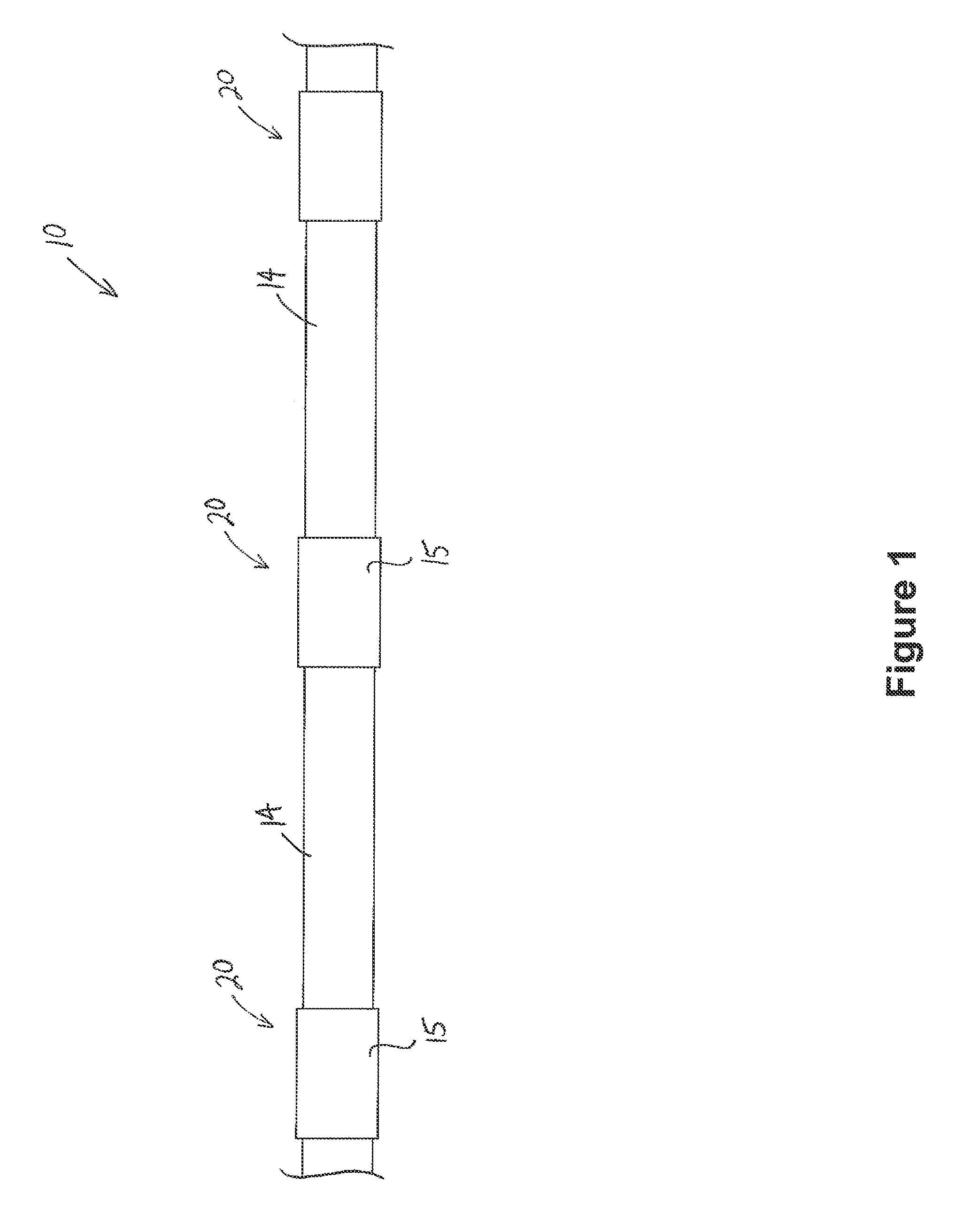
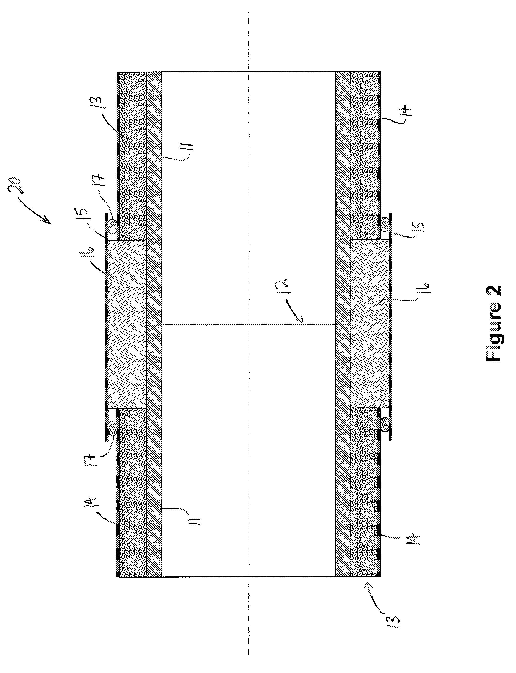
Due to thermal expansion, wind-induced vibration, aging, and other factors, the weather seals 17 between the shop-applied spiral wrap jacket 14 and the field-applied jacket 15 are particularly susceptible to failure.
However, this approach has several drawbacks.
Further, moisture sensors may be problematic as CUI indicators since they typically only indicate the immediate presence of moisture and not the past presence of moisture.
This often happens on pipelines that are cool (e.g., ˜60 F) as the temperature is not sufficient to drive the corrosion reaction at a rate to generate significant (detectable) corrosion.
Consequently, simple moisture sensors on these pipelines would be of little value.
As can be seen, the TRT inspection process is very time consuming and expensive.
Further, since corrosion is typically detected on only approximately 4% of inspections, much of the time and associated cost is spent inspecting CUI-susceptible locations that have not experienced detectable corrosion.

Method used


Image

  • Methods and devices for sensing corrosion under insulation (CUI)
  • Methods and devices for sensing corrosion under insulation (CUI)
  • Methods and devices for sensing corrosion under insulation (CUI)

Examples


Embodiment Construction

[0063]The following discussion is directed to various exemplary embodiments. However, one skilled in the art will understand that the examples disclosed herein have broad application, and that the discussion of any embodiment is meant only to be exemplary of that embodiment, and not intended to suggest that the scope of the disclosure, including the claims, is limited to that embodiment.

[0064]Certain terms are used throughout the following description and claims to refer to particular features or components. As one skilled in the art will appreciate, different persons may refer to the same feature or component by different names. This document does not intend to distinguish between components or features that differ in name but not function. The drawing figures are not necessarily to scale. Certain features and components herein may be shown exaggerated in scale or in somewhat schematic form and some details of conventional elements may not be shown in interest of clarity and concis...


PUM

PropertyMeasurementUnit
diameteraaaaaaaaaa
diameteraaaaaaaaaa
temperatureaaaaaaaaaa

Abstract

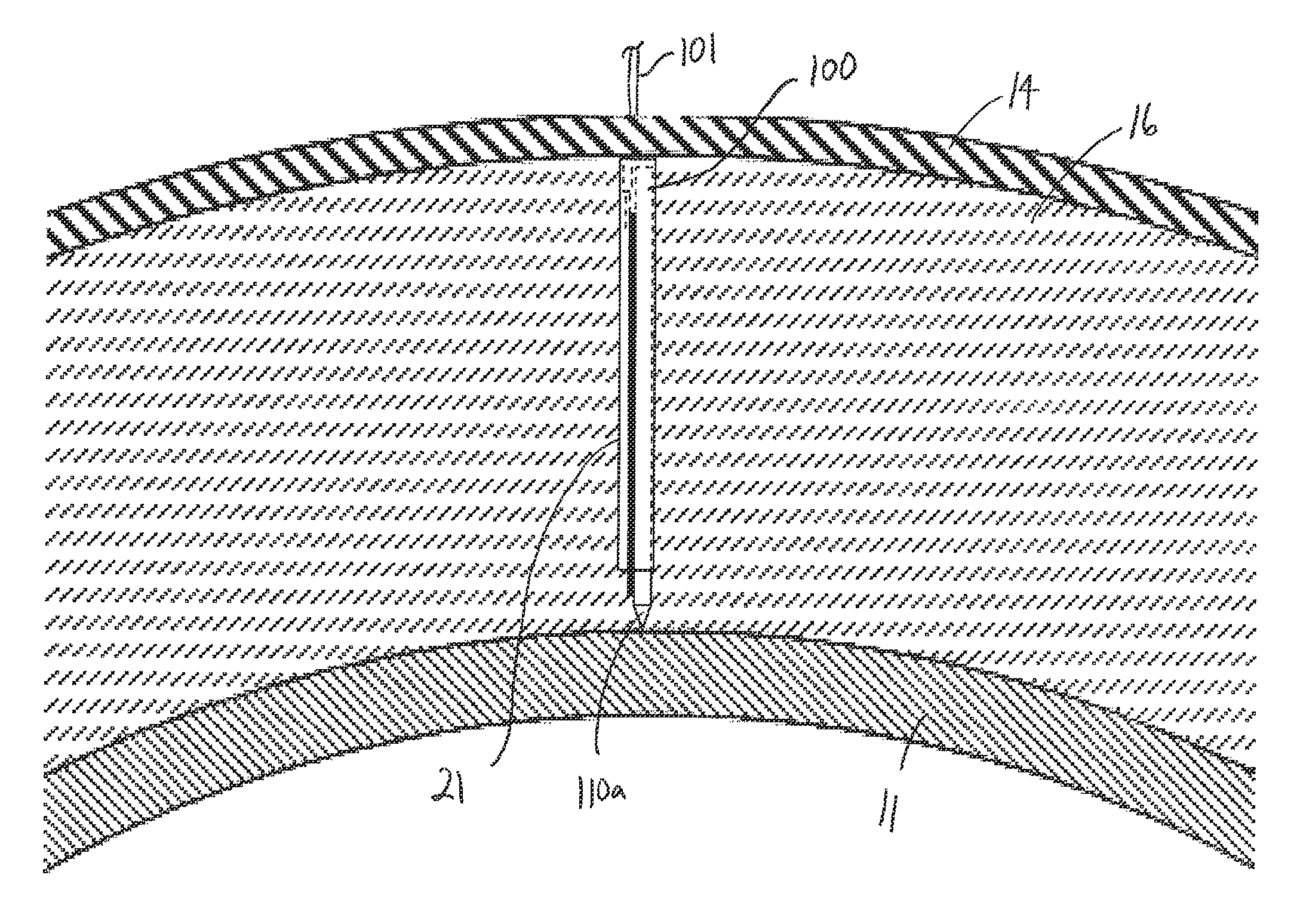
A method of sensing corrosion of a pipe covered by a layer of insulation comprises positioning a CUI sensor radially adjacent an outer surface of the pipe. The CUI sensor comprises a non-conductive base having a first end and a second end opposite the first end. In addition, the CUI sensor comprises a first test circuit mounted to the base. The first test circuit includes a first conductor, a second conductor, and a first testing element extending between the first conductor and the second conductor. Further, the method comprises exposing the first testing element to the same environment as the outer surface of the pipe. Still further, the method comprises determining whether the first testing element has corroded through. Moreover, the method comprises assessing whether corrosion of the pipe has occurred based on the determination of whether the first testing element has corroded through.

Description

CROSS-REFERENCE TO RELATED APPLICATIONS[0001]This application claims benefit of U.S. provisional patent application Ser. No. 61 / 379,769 filed Sep. 3, 2010, and entitled “Method and Apparatus for Sensing Corrosion Under Insulation (CUI),” which is hereby incorporated herein by reference in its entirety.STATEMENT REGARDING FEDERALLY SPONSORED RESEARCH OR DEVELOPMENT[0002]Not applicable.BACKGROUND[0003]1. Field of the Invention[0004]This invention relates generally to the field of corrosion sensing. More specifically, the invention relates to methods and devices for sensing corrosion under insulation.[0005]2. Background of the Technology[0006]Corrosion Under Insulation (CUI) is a form of localized corrosion that has plagued insulated steel pipelines in the chemical and oil / gas industries for years. CUI-susceptible locations are often the result of legacy pipeline construction techniques. In particular, above-ground pipelines may be insulated with shop-applied, foam-in-place polyurethan...

Claims


Application Information

Patent Timeline
Patent Type & Authority Patents(United States)
IPC IPC(8): G01N17/00
CPCG01N17/00G01N17/006G01N17/046G01N27/121G01N33/20G01N33/2045
Inventor BOHON, WILLIAM MARKPERKINS, ALLAN JOHN
Owner BP CORP NORTH AMERICA INC
Learn More