Interrupting chamber for high-voltage circuit breaker with improved arc blow-out

a high-voltage circuit breaker and interrupting chamber technology, which is applied in the direction of air-break switches, high-tension/heavy-dress switches, electrical apparatus, etc., can solve the problems of loss of blow-out gas to the exterior of the blow-out volume without, slow movement of the moving part of the interrupting chamber, and inability to reverse itsel

Active Publication Date: 2014-08-26
ALSTOM TECH LTD
View PDF17 Cites 5 Cited by
  • Summary
  • Abstract
  • Description
  • Claims
  • Application Information

AI Technical Summary

Benefits of technology

[0033]According to the invention, the loading of the valve makes it possible to blank off the hole when the overpressure exerted in the cavity is less than a predetermined value, the hole being a through hole in the channel defined between the insulating component and the arc contact, when the overpressure exerted in the cavity is greater than the predetermined value, the valve loading being carried out so as to conserve a sufficiently high overpressure in the cavity for the whole range of currents to be broken.
[0045]an additional ball type valve fitted on the fixed wall and enabling the passage of gas from the cavity of variable volume into the thermal expansion volume.
[0046]To avoid the escape of the hot gases produced into an area near to the moving arc contact assembly, during the breaking of strong currents, a non return check valve fitted in the channel defined between the insulating component and the arc contact may advantageously be provided.
[0056]It is possible to provide drive means in the interrupting chamber which enable the two pairs of contacts to be made moveable, the invention is thus applicable to chambers known as double motion chambers.

Problems solved by technology

Yet, if the pressure reached is excessive and becomes greater than the motive force delivered by the control to open the circuit breaker, the movement of the moving part of the interrupting chamber slows and can even reverse itself.
The solution proposed according to this document has the main drawback of reducing the overpressure for all the breakings carried out with long arc times, including those carried out with currents of low intensity with which a reduction of overpressure is not desired.
When the check valve 16, 17 opens, this solution has the drawback of causing a loss of blow-out gas to the exterior of the blow-out volume without being used for the blow-out of the arc.
This solution is thus not optimised.
But, the overpressure in the expansion volume is without effect on the displacement of the contacts and thus the energy that needs to be supplied by the control.
The major drawback of this solution resides in the fact that when the pin 1 has ceased to obstruct the channel 14, the compression volume empties itself permanently, including for currents of value ranging between 10 and 30% of the interrupting capacity of the circuit breaker, in an area 14 situated downstream of the main blow-out channel 12, far from the root of the arc 4.
Consequently, the blow-out carried out is not very efficient.
Another drawback is that the auto-pneumatic blow-out is exerted far from the root of the arc which takes place at the point referenced 8A in FIG. 1 and there is no aid to the rise in pressure in the volume 13 by thermal effect, the volumes 9 and 13 not communicating together (volumes not in hydraulic series).
This type of solution has not been applied industrially due to its reduced cutoff capacities.
The emptying thus takes place far from the root of the arc taking place at the end of the moving arc contact 2, and thus is not efficient for the breaking of the current.
The reduction in the operating stresses is thus limited.

Method used


Image

  • Interrupting chamber for high-voltage circuit breaker with improved arc blow-out
  • Interrupting chamber for high-voltage circuit breaker with improved arc blow-out
  • Interrupting chamber for high-voltage circuit breaker with improved arc blow-out

Examples


Embodiment Construction

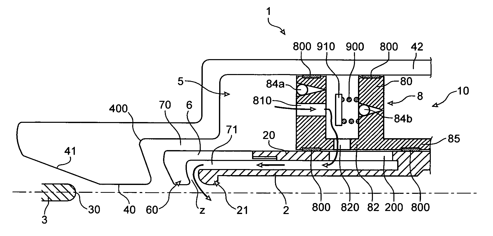
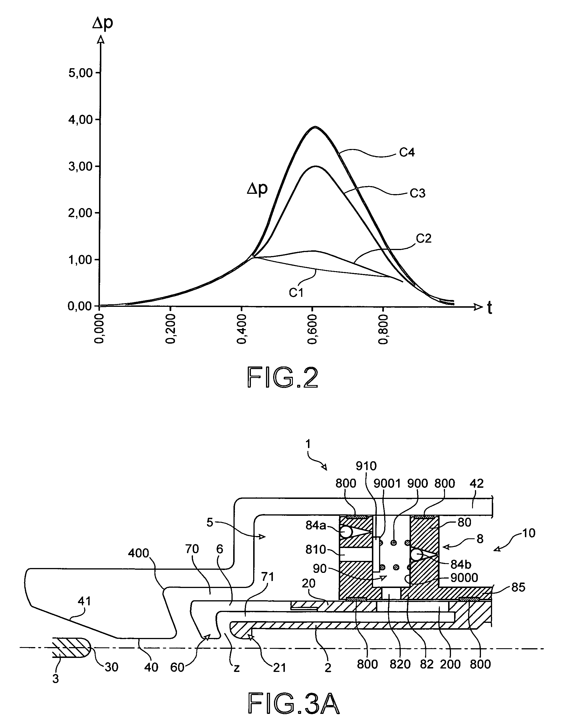
[0032]To this end, the invention relates to a interrupting chamber for a high-voltage circuit breaker, intended to break all currents of value less than or equal to the short circuit interrupting capacity of the circuit breaker, including asymmetric currents, the chamber comprising two pairs of contacts each comprising an arc contact and adapted to separate apart during an arc breaking, an insulating arc blow-out nozzle comprising a neck, the arc blow-out nozzle being integral with a pair of contacts constituting a moveable assembly, the interrupting chamber comprising an additional insulating component integral with the arc contact, itself integral with the nozzle and arranged between the part of the nozzle upstream of the neck and the arc contact so as to define two channels, the channel defined between the nozzle and the additional insulating component opening out permanently towards a cavity of variable volume, the volume of the cavity being variable under the action of a fixed ...


PUM


Abstract

The invention relates to an interrupting chamber for a high-voltage circuit breaker of preferably greater than at least 52 kV adapted to break all currents of value less than or equal to the short-circuit interrupting capacity of the circuit breaker, including asymmetric currents comprising an arc contact, an insulating arc blow-out nozzle having a through hole adapted to be blanked off by a valve, an insulating component which forms two channels, one of which is located between the insulating component and the arc contact, and wherein the hole is in communication with the channel.

Description

TECHNICAL FIELD[0001]The invention relates to interrupting chambers for high-voltage circuit breakers.[0002]It relates to the improvement of the arc blow-out induced by all currents of value less than or equal to the short circuit interrupting capacity of the circuit breaker, including asymmetric currents.[0003]It is more particularly connected with the optimisation of the exhaust route of the gases that contribute to the arc extinction.[0004]The main application targets high voltage circuit breakers greater than 52 kV and more particularly circuit breakers of rated voltage greater than or equal to 245 kV.PRIOR ART[0005]FIGS. 1A to 1C represent in longitudinal sectional view a interrupting chamber 1 of a high-voltage circuit breaker according to the prior art of auto-pneumatic blow-out type, respectively:[0006]in the position of closing of the contacts,[0007]in an intermediate position at the start of the opening operation in which the moving arc contact 2 begins to separate from th...

Claims


Application Information

Patent Timeline
Patent Type & Authority Patents(United States)
IPC IPC(8): H01H33/90
CPCH01H33/905H01H2033/906H01H2033/902H01H2033/908
Inventor DUFOURNET, DENIS
Owner ALSTOM TECH LTD
Why Eureka
Try Eureka