Supercharge Your Innovation With Domain-Expert AI Agents!

Multichannel audio coder and decoder

a multi-channel audio and coder technology, applied in the field of multi-channel audio coder and decoder, coding and decoding of audio and speech signals, can solve the problems of inability to define channel separation, and inability to achieve level and time alignment. the effect of better channel separation

Active Publication Date: 2014-08-26
PIECE FUTURE PTE LTD
View PDF10 Cites 1 Cited by
  • Summary
  • Abstract
  • Description
  • Claims
  • Application Information

AI Technical Summary

Benefits of technology

This approach enables better-defined channel separation and higher-quality encoding of multi-channel signals, reducing bandwidth requirements and improving audio depth and fidelity in wireless communication systems.

Problems solved by technology

Multi-channel systems as hinted above have an inherent problem in that an N channel / microphone source system when directly encoded produces a bit stream which requires approximately the N times the bandwidth of a single channel.
This multi-channel bandwidth requirement is typically prohibitive for wireless communication systems.
However this produces a problem in that the level and time alignment differs for different time and frequency elements.
However, this is computationally difficult and requires a large amount of processing power.
This type of system, due to the encoding, produces a less than optimal audio image and is unable to produce the depth of audio that a multi-channel system can produce

Method used


Image

  • Multichannel audio coder and decoder
  • Multichannel audio coder and decoder
  • Multichannel audio coder and decoder

Examples


Embodiment Construction

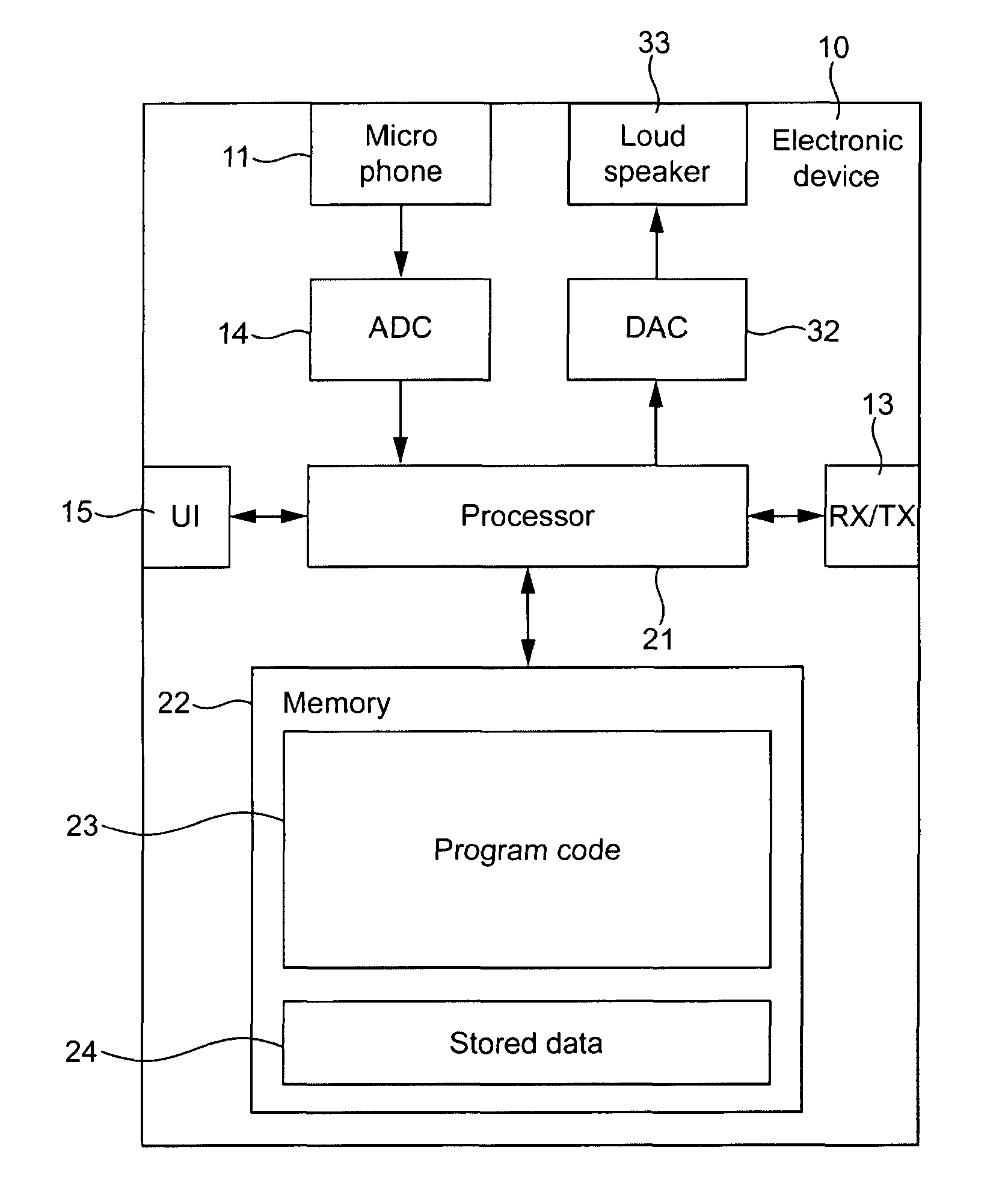
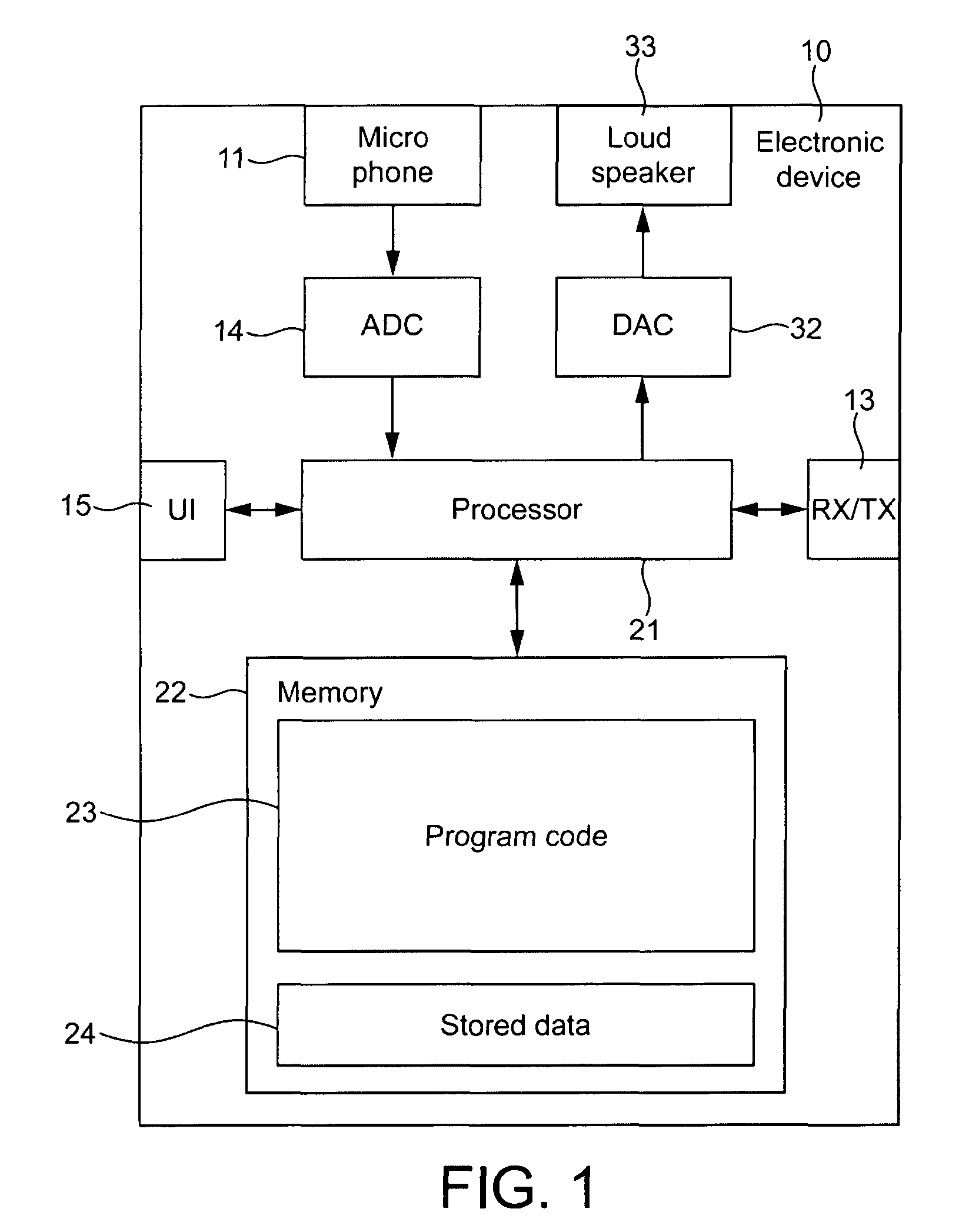
[0072]The following describes in further detail suitable apparatus and possible mechanisms for the provision of enhancing encoding efficiency and signal fidelity for an audio codec. In this regard reference is first made to FIG. 1 which shows a schematic block diagram of an exemplary apparatus or electronic device 10, which may incorporate a codec according to an embodiment of the invention.

[0073]The electronic device 10 may for example be a mobile terminal or user equipment of a wireless communication system.

[0074]The electronic device 10 comprises a microphone 11, which is linked via an analogue-to-digital converter 14 to a processor 21. The processor 21 is further linked via a digital-to-analogue converter 32 to loudspeakers 33. The processor 21 is further linked to a transceiver (TX / RX) 13, to a user interface (UI) 15 and to a memory 22.

[0075]The processor 21 may be configured to execute various program codes. The implemented program codes may comprise encoding code routines. Th...


PUM


Abstract

There is disclosed inter alia a method for dividing a first and a second signal into a plurality of time frames and determining for each time frame a first time delay associated with a delay between a start of a time frame of the first signal and the second signal, and determining a second time delay associated with a delay between an end of a time frame of the first signal and the second signal. Then selecting from the second signal at least one sample in a block of samples between the first time delay and the second time delay and stretching the selected at least one sample to equal the number of samples of the time frame of the first signal.

Description

RELATED APPLICATION[0001]This application was originally filed as PCT Application No. PCT / EP2008 / 060536 on Aug. 11, 2008, which is incorporated herein by reference in its entirety.FIELD OF THE INVENTION[0002]The present invention relates to apparatus for coding and decoding and specifically but not only for coding and decoding of audio and speech signalsBACKGROUND OF THE INVENTION[0003]Spatial audio processing is the effect of an audio signal emanating from an audio source arriving at the left and right ears of a listener via different propagation paths. As a consequence of this effect the signal at the left ear will typically have a different arrival time and signal level to that of the corresponding signal arriving at the right ear. The difference between the times and signal levels are functions of the differences in the paths by which the audio signal travelled in order to reach the left and right ears respectively. The listener's brain then interprets these differences to give ...

Claims


Application Information

Patent Timeline
Patent Type & Authority Patents(United States)
IPC IPC(8): H04R5/00G10L19/00G10L19/008
CPCG10L19/008
Inventor VILERMO, MIIKKA TAPANITAMMI, MIKKO TAPIO
Owner PIECE FUTURE PTE LTD
Features
  • R&D
  • Intellectual Property
  • Life Sciences
  • Materials
  • Tech Scout
  • Unparalleled Data Quality
  • Higher Quality Content
  • 60% Fewer Hallucinations
Learn More