Optical network unit with redundant reverse powering from customer premises equipment with alarm fault discrimination indicative for power fault condition

Active Publication Date: 2014-08-26
ADTRAN
View PDF23 Cites 57 Cited by
  • Summary
  • Abstract
  • Description
  • Claims
  • Application Information

AI Technical Summary

Problems solved by technology

In one example, the external CPE power supply faults comprise an AC power input failure at the CPE or low battery voltage.

Method used


Image

  • Optical network unit with redundant reverse powering from customer premises equipment with alarm fault discrimination indicative for power fault condition
  • Optical network unit with redundant reverse powering from customer premises equipment with alarm fault discrimination indicative for power fault condition
  • Optical network unit with redundant reverse powering from customer premises equipment with alarm fault discrimination indicative for power fault condition

Examples


Embodiment Construction

[0017]Different embodiments will now be described more fully hereinafter with reference to the accompanying drawings, in which preferred embodiments are shown. Many different forms can be set forth and described embodiments should not be construed as limited to the embodiments set forth herein. Rather, these embodiments are provided so that this disclosure will be thorough and complete, and will fully convey the scope to those skilled in the art.

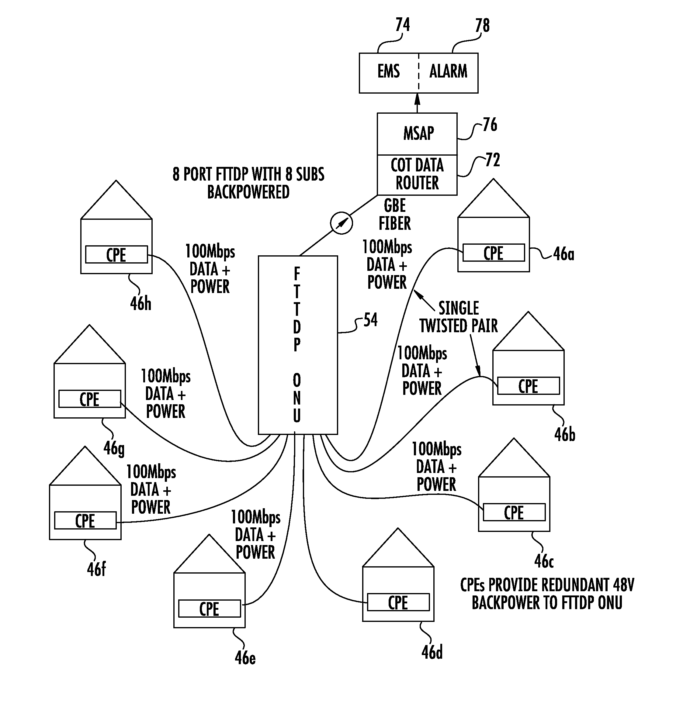
[0018]Reverse powering systems are used to power remote standalone devices over network interfaces without requiring a dedicated power source on site. As explained below with reference to FIGS. 1-8, the power is driven on the same wires as the communications channel between the devices. These reverse power systems save service providers money by obviating the need to have an AC power drop / power meter installed at the reverse powered device location.

[0019]In the redundant reverse powered communication system described relative to FIGS. 1-8, m...


PUM


Abstract

An optical communication system includes a plurality of Customer Premises Equipment (CPE) each having a reverse power supply and configured to transmit and receive data and provide power over a wire pair connected thereto. An optical network unit is formed as a plurality of communication ports. A respective communication port is configured to provide communications data service with a respective CPE by transmitting and receiving data therewith. A power management circuit is connected to the communication ports and configured to receive power provided by each reverse power supply at a respective CPE and manage power consumption in the ONU. A processor is configured to receive alarms generated by at least one of a CPE and ONU indicative of a power fault condition and process the alarms and discriminate between different power fault conditions.

Description

FIELD OF THE INVENTION[0001]The present invention relates to communications systems, and more particularly, this invention relates to powering an Optical Network Unit (ONU).BACKGROUND OF THE INVENTION[0002]Current fiber fed Optical Network Unit (ONU) type telecommunications systems require expensive to install and maintain power rectifiers and AC mains meter and service to power the ONU equipment. Power over Ethernet (PoE) provides single port powering over Ethernet service cables. There are yet other systems where a network element receives power and data over electrical lines from a Customer Premises Equipment (CPE). There is a desire, however, for greater management control and redundancy that is not provided by these types of systems.[0003]This can be provided by a redundant reverse power communication system where multiple CPE devices push power up multiple service pairs to power a fiber-fed remote ONU. In such system, it is desirable to be able to discriminate the intentional ...

Claims


Application Information

Patent Timeline
Patent Type & Authority Patents(United States)
IPC IPC(8): H04B10/00
CPCH04B10/00H04B10/27H04B10/808
Inventor SMITH, BRIAN C.ROBINSON, STEVEN M.
Owner ADTRAN
Why Eureka
Try Eureka