
Sandal with removable straps

a technology of sandals and straps, applied in the field of sandals with removable straps, can solve the problems of affecting the service life of sandals, and affecting the service life of sandals, and achieve the effect of simple design and manufactur

Inactive Publication Date: 2014-09-02
MIZRAHI SHAPIRO EDUARDO NURI
View PDF9 Cites 7 Cited by
  • Summary
  • Abstract
  • Description
  • Claims
  • Application Information

AI Technical Summary

Benefits of technology

[0007]Considering the prior art drawbacks, it is an object of the present invention to provide a sandal with removable straps, of a very simple design and manufacture, but practical to remove and exchange the straps of the sole without using tools or devices.
[0008]Another object of the present invention is to provide a sandal with removable straps allowing the user having a single pair of soles and multiple removable straps in different styles and colors.
[0009]Yet another object of the present invention is to provide a sandal with removable straps allowing a simple and non-expensive change of the damaged straps, since there is no need to change the whole sandal.BRIEF DESCRIPTION OF THE INVENTION
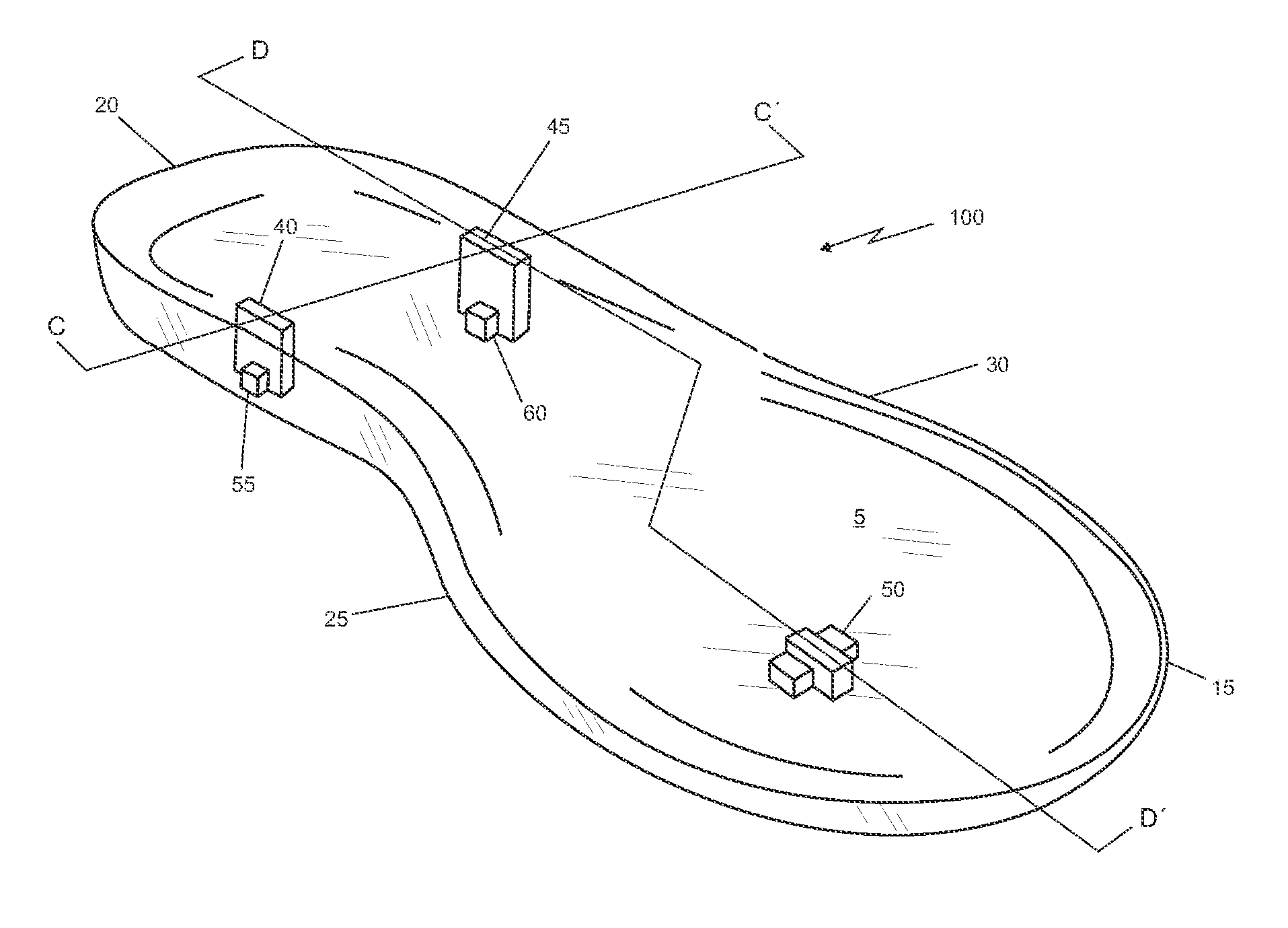
[0011]The sole includes a first plurality of orifices which longitudinal axis is parallel to said sole longitudinal axis, which extends from the upper surface to the lower surface throughout the sole thickness. Likewise, the sole includes a second plurality of orifices which longitudinal axis is perpendicular to the sole longitudinal axis, which extend from the lower surface to the inside of the sole thickness without passing through. Said orifices from the first plurality are perpendicularly oriented with the orifices of the second plurality forming a “cross”, thereby allowing the removable attachment of the holding means to the sole.

Problems solved by technology

However, a drawback in this type of sandals is that the hook-engaging strip ends and the sole groove structure are more complex, thus, the manufacturing tool kit is more expensive.
This kind of sandals have the great drawback of including screws to secure the top portion rear attachment ends in “Y” shape to the sole, wherein the screw threads may wear out with time and stop working.

Method used


Image

  • Sandal with removable straps
  • Sandal with removable straps
  • Sandal with removable straps

Examples


Embodiment Construction

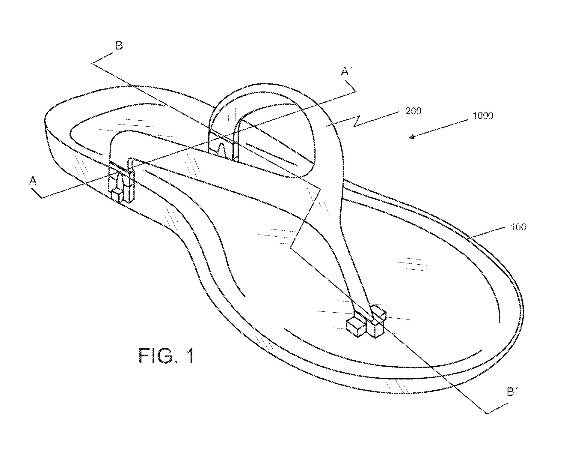
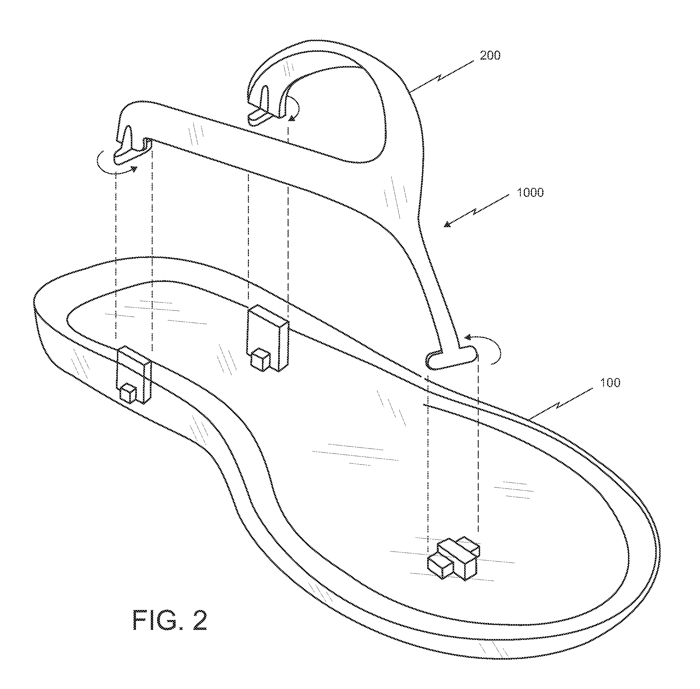
[0028]Particularly referring to the appended drawings, and specifically to FIG. 1, a sandal 1000 is shown, which comprises a sole 100 holding a user's foot by using holding means 200 located at the upper portion of said sandal 1000, which are removable attached to the sole 100.

[0029]Now, specifically referring to FIGS. 2 to 7 of the appended drawings, a sole 100 is shown therein, with the holding means 200 removed, wherein said sole 100 has an upper surface 5 and a lower surface 10. Likewise, the sole 100 also has a front portion 15 and a rear portion 20, along with to a left side edge 25 and a right side edge 30.

[0030]In addition, the sole 100 includes a first plurality of orifices having a geometrical shape, preferably a rectangular shape, which longitudinal axis is parallel to the sole 100 longitudinal axis, which extend from the upper surface 5 to the lower surface 10, i.e., pass throughout said sole 100 thickness. From said first plurality of orifices, a first orifice 35 is loc...


PUM


Abstract

A sandal is described, which includes a sole, straps holding the sole to a user's foot, and a first a second plurality of orifices located at the sole, wherein the orifices of the first plurality are perpendicularly oriented to the orifices of the second plurality forming a “cross” and the straps, in order to be attached to the sole, are removable inserted into the cross formed by the first and second plurality of orifices.

Description

TECHNICAL FIELD[0001]The present invention is related to the techniques employed in the shoe industry, for the design and manufacture of articles to cover and keep safe the foot, and more particularly, it is related to a sandal with removable straps.BACKGROUND OF THE INVENTION[0002]Shoes are part of the garments used to cover and protect feet, having many shapes such as, but not limited to, shoes, high heels, boots, sandals or tennis.[0003]Shoes are used for various reasons, including feet protection, hygiene or decoration only.[0004]Often socks or stockings are used with shoes, or on the contrary, bare feet when using sandals.[0005]In the prior art there are patent documents describing sandals with exchangeable strips or straps, such as U.S. Pat. No. 7,222,441 related to a sandal with an interchangeable strip including a sole portion and a section encasing or surrounding the instep. The section encasing the instep is removable attached to a first and second side ends, adjacent to t...

Claims


Application Information

Patent Timeline
Patent Type & Authority Patents(United States)
IPC IPC(8): A43B3/12A43B3/24
CPCA43B3/242A43B3/12A43B3/122A43B3/103A43B3/244A43B1/0027
Inventor MIZRAHI-SHAPIRO, EDUARDO, NURI
Owner MIZRAHI SHAPIRO EDUARDO NURI
Learn More