Supercharge Your Innovation With Domain-Expert AI Agents!

Pivot ring for a manual clutch

a technology of pivoting ring and clutch, which is applied in the direction of friction clutches, interengaging clutches, clutches, etc., can solve the problems of reducing the operating point of the clutch, reducing the working load, and high temperature gradient throughout the pressure plate, so as to reduce the change of the height of the diaphragm spring

Inactive Publication Date: 2014-09-02
SCHAEFFLER TECH AG & CO KG
View PDF2 Cites 1 Cited by
  • Summary
  • Abstract
  • Description
  • Claims
  • Application Information

AI Technical Summary

Benefits of technology

The present invention is a pivot ring for a clutch assembly that allows for rotational movement between a pressure plate and a diaphragm spring. This rotational freedom ensures consistent operation of the clutch in high energy events. The pivot ring also helps to maintain the height of the diaphragm spring during high-speed events.

Problems solved by technology

When a high energy event occurs in the clutch, it results in a high temperature gradient throughout the pressure plate.
This causes the pressure plate to distort from a flat or concave shape to a convex shape creating a geometrical height change at the connection between the pressure plate and the diaphragm spring which results in a lower operating point of the clutch.
Moreover, the change in the height of the diaphragm spring causes lower working loads and less torque capacity of the clutch.
Furthermore, the change in the height of the fingers of the diaphragm spring can cause issues at the vehicle system level, such as the clutch pedal not returning when the operator tries to re-engage the clutch.

Method used


Image

  • Pivot ring for a manual clutch
  • Pivot ring for a manual clutch
  • Pivot ring for a manual clutch

Examples


Embodiment Construction

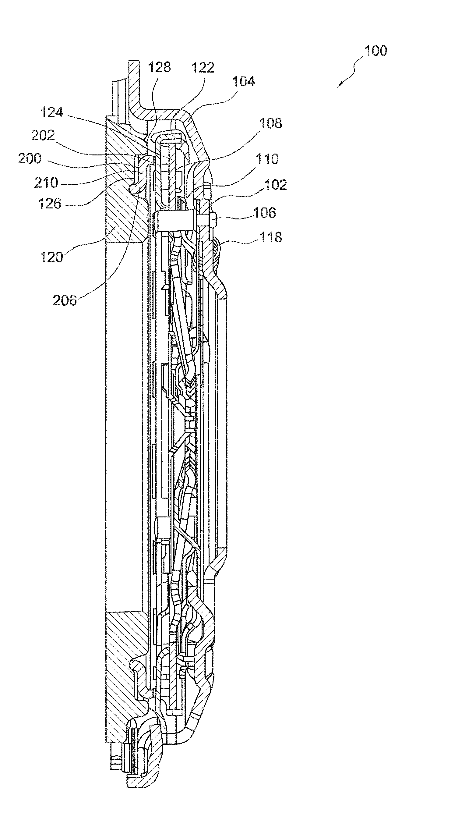
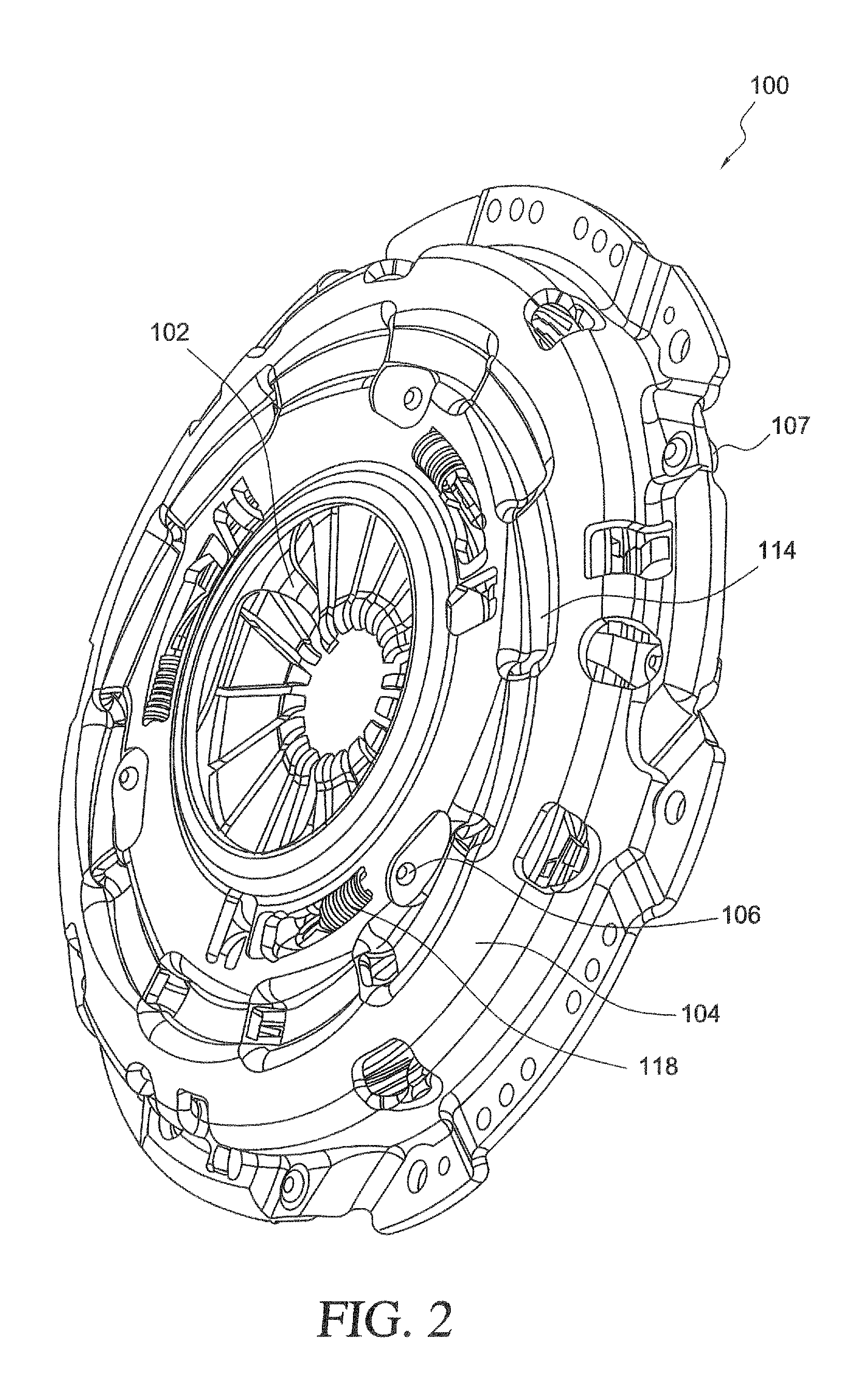
[0050]At the outset, it should be appreciated that like drawing numbers appearing in different drawing views identify identical, or functionally similar, structural elements. Furthermore, it should be understood that the invention is not limited only to the particular embodiments, methodologies, materials, and modifications described herein and, as such, may vary. It is also understood that the terminology used herein is for the purpose of describing particular aspects only, and is not intended to limit the scope of the present invention.

[0051]Unless defined otherwise, all technical and scientific terms used herein have the same meaning as commonly understood to one of ordinary skill in the art. Although any methods, devices, or materials similar or equivalent to those described herein can be used in the practice or testing of the invention, the following example methods, devices, and materials are now described.

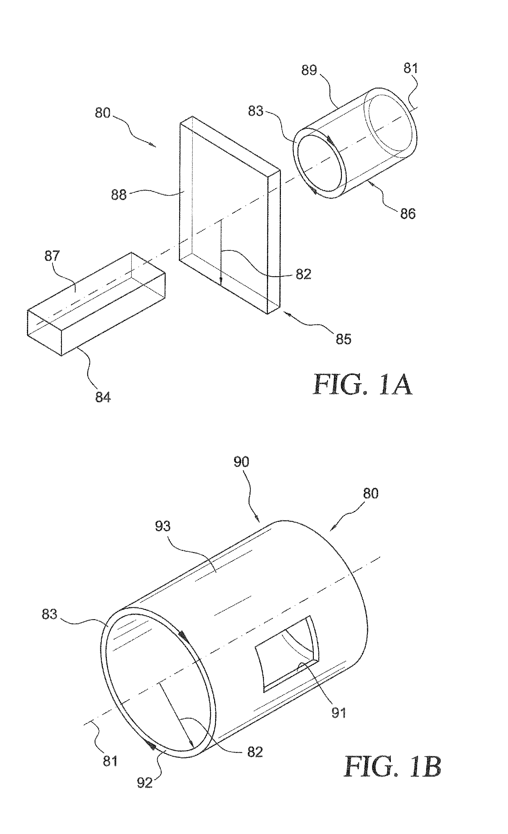
[0052]FIG. 1A is a perspective view of a cylindrical coordinate system ...


PUM


Abstract

A pivot ring for a clutch assembly which has a first annular segment, a second annular segment, and a radial segment. The first annular segment has a first face on a front side of the pivot ring and the second annular segment has a second face, predominately opposing the first face, on a back side of the ring. The radial segment is disposed between the first annular segment and the second annular segment, connecting the first annular segment and the second annular segment. The first annular segment, the second annular segment, or both the first annular segment and the second annular segment can include axial protrusions with arcuately shaped pivot portions. Preferably, in the clutch assembly, the pivot ring is disposed between the diaphragm spring and the pressure plate, allowing for rotational freedom between the pressure plate and the diaphragm spring.

Description

[0001]This application claims the priority of U.S. Provisional Patent Application Nos. 61 / 330,714 filed May 3, 2010 and 61 / 383,481 filed Sep. 16, 2010, the contents of both applications are incorporated by reference herein.FIELD OF THE INVENTION[0002]The invention relates generally to a clutch assembly and more specifically to a pivot ring for a clutch assembly used in self-adjusting and non-adjusting clutches.BACKGROUND OF THE INVENTION[0003]Self-adjusting and non-adjusting clutches are known. These clutches typically have a single pivoting connection between a pressure plate and a diaphragm spring. When a high energy event occurs in the clutch, it results in a high temperature gradient throughout the pressure plate. This causes the pressure plate to distort from a flat or concave shape to a convex shape creating a geometrical height change at the connection between the pressure plate and the diaphragm spring which results in a lower operating point of the clutch. The change in the...

Claims


Application Information

Patent Timeline
Patent Type & Authority Patents(United States)
IPC IPC(8): F16D13/70F16D13/58
CPCF16D13/585F16D13/757
Inventor HODGE, MICHAELHEMPHILL, JEFFREY
Owner SCHAEFFLER TECH AG & CO KG
Features
  • R&D
  • Intellectual Property
  • Life Sciences
  • Materials
  • Tech Scout
  • Unparalleled Data Quality
  • Higher Quality Content
  • 60% Fewer Hallucinations
Learn More