System and method for enhanced watch dog in solar panel installations

a solar panel and watch dog technology, applied in powerline communication applications, instruments, process and machine control, etc., can solve the problems of presenting the potential safety risks associated with presenting its own safety risk, and presenting the potential safety risks of working in a poorly lit environmen

Active Publication Date: 2014-09-02
NEWLIGHT CAPITAL LLC
View PDF92 Cites 146 Cited by
  • Summary
  • Abstract
  • Description
  • Claims
  • Application Information

AI Technical Summary

Problems solved by technology

When a photovoltaic panel or laminate is exposed to direct or diffuse light, a lethal voltage potential may be present.
However, this approach proposes its own safety risk from having the wind catch the tarpaulin and pull installation personnel off the roof as they try to control the unstable sheet material against the wind.
This approach presents the potential safety risks associated from working in a poorly lighted environment.
In addition to the potential personnel safety issues there are also significant risks to equipment and hardware.
Connecting or disconnecting energized plugs can cause arcing and damage to these connectors, junction boxes, and other electrical components.
That limitation inhibits them from installing more solar panel modules, often referred to as “modules” or “panels,” in series to reduce the cost of combiner boxes or string inverters.
When solar modules are connected in series or in mesh configurations, there can be a problem in which weaker modules not only produce less energy but also affect other modules' capabilities to deliver energy in the same string or wiring section.
If certain wires are disconnected, through theft, vandalism, accident, natural forces, or any other cause, voltages may rise to an unacceptable, even dangerous, level.
In addition to locally generated problems that can affect the safety of the system and or people working at or near the system, other, more regionally created problems may cause safety issues, including, for example, floods, forest fires or neighborhood fires, earthquakes, landslides, etc.

Method used


Image

  • System and method for enhanced watch dog in solar panel installations
  • System and method for enhanced watch dog in solar panel installations
  • System and method for enhanced watch dog in solar panel installations

Examples


Embodiment Construction

[0031]The following description and drawings are illustrative and are not to be construed as limiting. Numerous specific details are described to provide a thorough understanding. However, in certain instances, well known or conventional details are not described in order to avoid obscuring the description. References to one or an embodiment in the present disclosure are not necessarily references to the same embodiment; and, such references mean at least one.

[0032]The use of headings herein are merely provided for ease of reference, and shall not be interpreted in any way to limit this disclosure or the following claims.

[0033]Reference in this specification to “one embodiment” or “an embodiment” means that a particular feature, structure, or characteristic described in connection with the embodiment is included in at least one embodiment of the disclosure. The appearances of the phrase “in one embodiment” in various places in the specification are not necessarily all referring to t...


PUM


Abstract

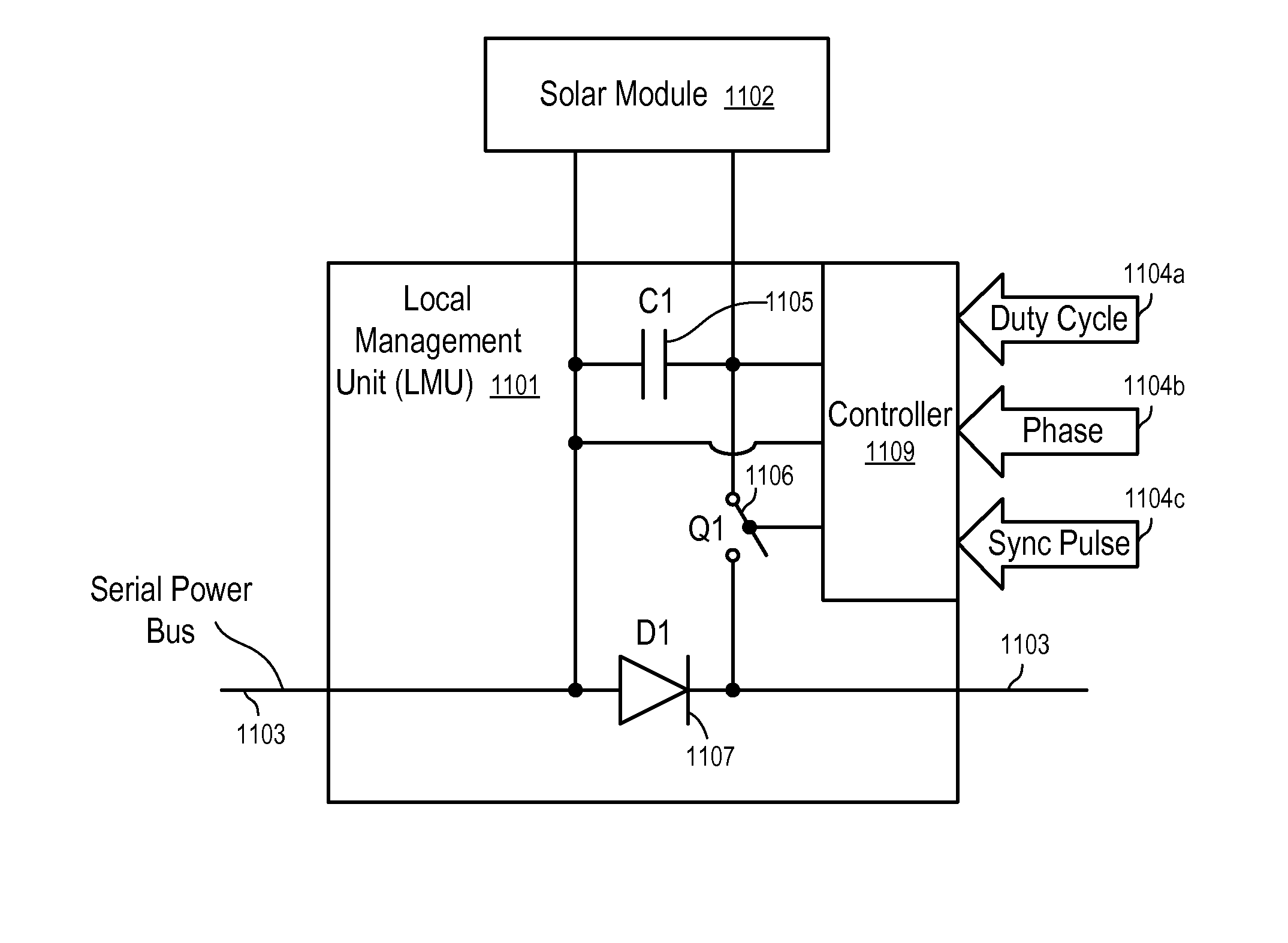
A system and method for automated shutdown, disconnect, or power reduction of solar panels. A system of solar panels includes one or more master management units (MMUs) and one or more local management units (LMUs). The MMUs are in communication with the LMUs with the MMUs and LMUs “handshaking” when the system is in operation. The MMUs are connected to one or more controllers which in turn are connected to emergency detection sensors. Upon a sensor detection of an emergency, the associated MMU is notified which in turn instructs associated LMUs to take appropriate action. In the event that communication with the MMUs has been cut off, the LMUs take the initiative to shutdown, disconnect, or reduce the output of associated string(s) of solar panels.

Description

CROSS-REFERENCE TO RELATED APPLICATIONS[0001]The present application is a non-provisional application which claims the benefit of U.S. Provisional Application Ser. No. 61 / 343,155, filed Apr. 22, 2010, entitled “SYSTEM AND METHOD FOR ENHANCED WATCH DOG IN SOLAR PANEL INSTALLATIONS,” the entire contents of which are incorporated by reference as if fully set forth herein. The present application is a non-provisional application which is a continuation-in-part of U.S. patent application Ser. No. 12 / 254,780, filed Oct. 20, 2008, entitled “APPARATUSES AND METHODS TO REDUCE SAFETY RISKS ASSOCIATED WITH PHOTOVOLTAIC SYSTEMS,” now U.S. Pat. No. 7,884,278, which claims the benefit of U.S. Provisional Application Ser. No. 61 / 001,587, filed Nov. 2, 2007, entitled “PHOTOVOLTAIC SAFETY SWITCH,” the entire contents of which disclosures are incorporated by reference as if fully set forth herein. The present application is a non-provisional application which is a continuation-in-part of U.S. patent ...

Claims


Application Information

Patent Timeline
Patent Type & Authority Patents(United States)
IPC IPC(8): G05F3/06
CPCH02S50/00H01L31/02021Y02E10/50G01R31/00H04B2203/5458H02S50/10Y02E10/56H02J3/38
Inventor HADAR, RONARDITI, SHMUELBICKFORD, JAMES
Owner NEWLIGHT CAPITAL LLC
Why Eureka
Try Eureka