
Systems and methods for remote or local shut-off of a photovoltaic system

a photovoltaic system and remote or local shut-off technology, applied in the field of photovoltaic systems, can solve the problems of affecting the installation of more solar panel modules, and weaker modules not only generating less energy

Active Publication Date: 2014-10-07
NEWLIGHT CAPITAL LLC
View PDF101 Cites 161 Cited by
  • Summary
  • Abstract
  • Description
  • Claims
  • Application Information

AI Technical Summary

Benefits of technology

The patent describes systems and methods for remotely or locally shutting down a photovoltaic system. The technical effect is the ability to efficiently control the operation of multiple solar modules through a central controller that receives a shut-down signal from a user device. This allows for flexible and safe shut-down procedures, improving operational efficiency and safety.

Problems solved by technology

When a photovoltaic panel or laminate is exposed to direct or diffuse light, a lethal voltage potential may be present.
That limitation inhibits them from installing more solar panel modules, often referred to as “modules” or “panels,” in series to reduce the cost of combiner boxes or string inverters.
When solar modules are connected in series or in mesh configurations, there can be a problem in which weaker modules not only produce less energy, but also affect other modules' capabilities to deliver energy in the same string or wiring section.
Also, potential danger from these high voltages may exist in various types of situations.
For example, first responders, solar array installers, and maintenance personnel operating near solar arrays can be exposed to dangerous or lethal voltages.
The danger can be even higher if certain wires are disconnected through theft, vandalism, accident, natural forces, or other causes.
However, the systems used to turn off a solar array in an emergency may sometimes be damaged or disabled by the emergency (e.g., fire).

Method used


Image

  • Systems and methods for remote or local shut-off of a photovoltaic system
  • Systems and methods for remote or local shut-off of a photovoltaic system
  • Systems and methods for remote or local shut-off of a photovoltaic system

Examples


Embodiment Construction

[0026]The following description and drawings are illustrative and are not to be construed as limiting. Numerous specific details are described to provide a thorough understanding. However, in certain instances, well known or conventional details are not described in order to avoid obscuring the description. References to one or an embodiment in the present disclosure are not necessarily references to the same embodiment; and, such references mean at least one.

[0027]Reference in this specification to “one embodiment” or “an embodiment” means that a particular feature, structure, or characteristic described in connection with the embodiment is included in at least one embodiment of the disclosure. The appearances of the phrase “in one embodiment” in various places in the specification are not necessarily all referring to the same embodiment, nor are separate or alternative embodiments mutually exclusive of other embodiments. Moreover, various features are described which may be exhibi...


PUM


Abstract

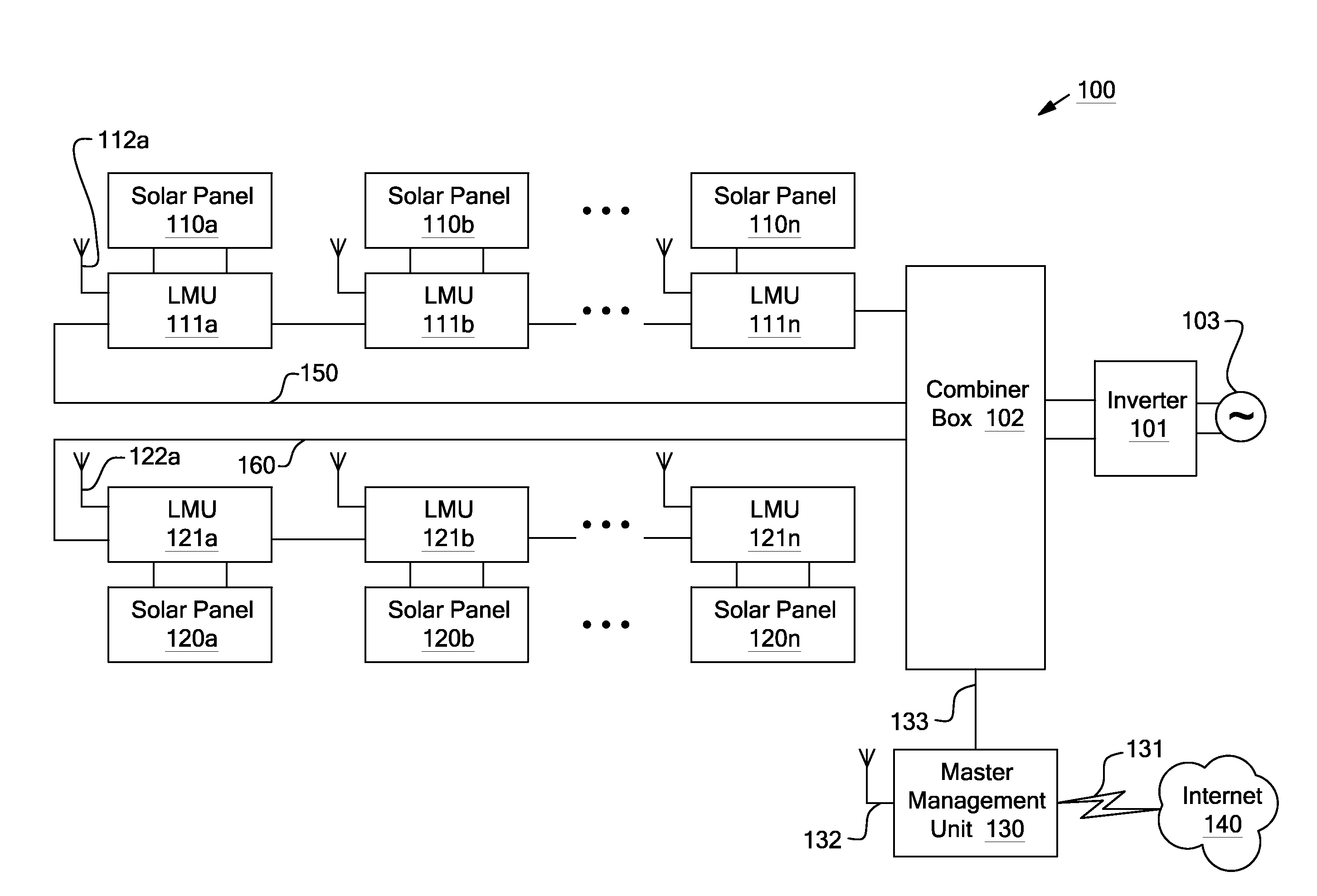
Systems and methods for shut-down of a photovoltaic system. In one embodiment, a method implemented in a computer system includes: communicating, via a central controller, with a plurality of local management units (LMUs), each of the LMUs coupled to control a respective solar module; receiving, via the central controller, a shut-down signal from a user device (e.g., a hand-held device, a computer, or a wireless switch unit); and in response to receiving the shut-down signal, shutting down operation of the respective solar module for each of the LMUs.

Description

CROSS-REFERENCE TO RELATED APPLICATIONS[0001]The present application is a continuation-in-part of U.S. Non-Provisional application Ser. No. 12 / 895,745, filed Sep. 30, 2010, entitled “SYSTEMS AND METHODS FOR A COMMUNICATION PROTOCOL BETWEEN A LOCAL CONTROLLER AND A MASTER CONTROLLER,” by Makhota et al., which itself claims priority to U.S. Provisional Application Ser. No. 61 / 335,004, filed Dec. 29, 2009, entitled “SYSTEM AND METHOD FOR AN ENHANCED PROTOCOL BETWEEN A LOCAL CONTROLLER AND A MASTER CONTROLLER,” by Makhota et al., the entire contents of which applications are incorporated by reference as if fully set forth herein.[0002]The present application is related to U.S. Provisional Application Ser. No. 61 / 277,867, filed Sep. 29, 2009, entitled “SYSTEM AND METHOD FOR REMOTE OR LOCAL SHUT-OFF OF SOLAR PANEL SYSTEMS,” by Makhota et al., the entire contents of which application are incorporated by reference as if fully set forth herein.[0003]The present application is also related to...

Claims


Application Information

Patent Timeline
Patent Type & Authority Patents(United States)
IPC IPC(8): G05B11/01G05B23/02G06F11/07H01L31/02H01L31/042
CPCH01L31/02021G06F11/0793Y02E10/50G06F11/0757G06F11/0736G05B9/02Y10T307/76H02J1/00Y02E10/56H02J3/38H02S40/30H02M7/44
Inventor MAKHOTA, MAXYMEIZIPS, DANIELKIKINIS, DAN
Owner NEWLIGHT CAPITAL LLC
Learn More