
Inverted pendulum type vehicle, and control method of inverted pendulum type vehicle

a technology of inverted pendulum and control method, which is applied in the direction of cycle equipment, cycle stands, instruments, etc., to achieve the effect of easy turning

Active Publication Date: 2014-09-02
HONDA MOTOR CO LTD
View PDF14 Cites 11 Cited by
  • Summary
  • Abstract
  • Description
  • Claims
  • Application Information

AI Technical Summary

Benefits of technology

[0008]The present invention has been made in view of such background, and aims at providing an inverted pendulum type vehicle and a control method of the inverted pendulum type vehicle in which an occupant is capable of turning the vehicle easily, without requiring skillful maneuvering technique and the like of the occupant.
[0019]According to the present invention, in the case where the turning of the inverted pendulum type vehicle is difficult, such as in the travel stopped state or the semi-travel stopped state, the desired tilt angle is set so that the magnitude of the moving velocity component of the traveling motion unit in the lateral direction becomes larger. Further, by controlling the steering direction of the wheel for performing turning according to the turning command, the rolling direction of the wheel becomes in the state changed with respect to the direction of the moving velocity vector of the traveling motion unit. Therefore, when the inverted pendulum type vehicle travels, the inverted pendulum type vehicle may be easily turned, without requiring the skillful maneuvering technique of the occupant and the like.

Problems solved by technology

Specifically, in a state where the inverted pendulum type vehicle is stopped, or in a semi-travel stopped state in which the inverted pendulum type vehicle is traveling at a low speed such as in a travel velocity lower than a predetermined value preliminarily set, it had been difficult even for the skilled rider to perform turning of the inverted pendulum type vehicle.

Method used


Image

  • Inverted pendulum type vehicle, and control method of inverted pendulum type vehicle
  • Inverted pendulum type vehicle, and control method of inverted pendulum type vehicle
  • Inverted pendulum type vehicle, and control method of inverted pendulum type vehicle

Examples


Embodiment Construction

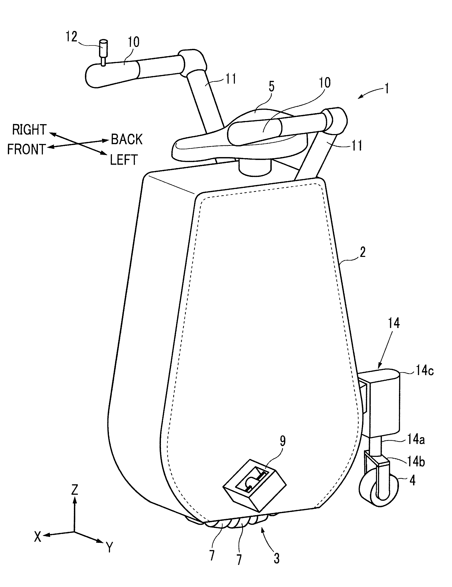
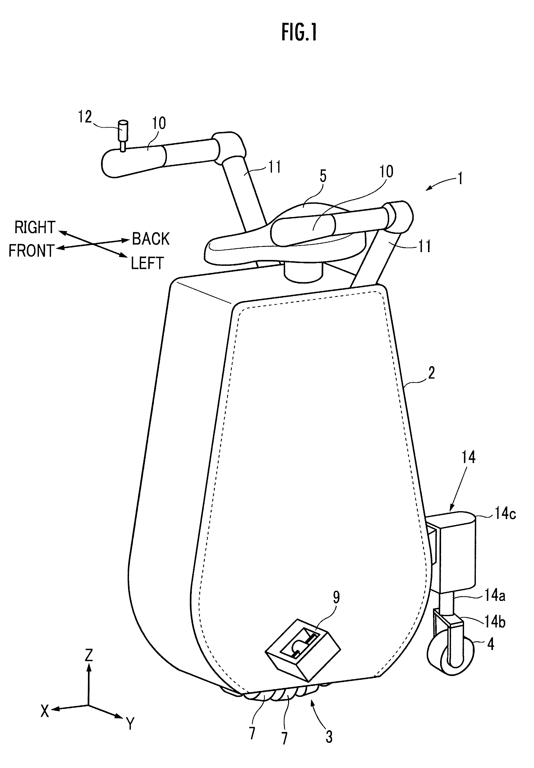
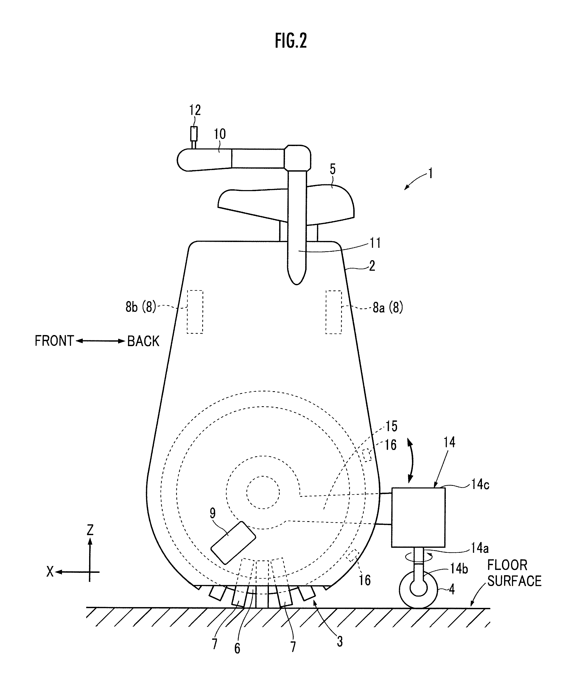
[0030]An inverted pendulum type vehicle of an embodiment of the present invention will be described. As illustrated in FIG. 1 and FIG. 2, an inverted pendulum type vehicle 1 according to the present embodiment (hereinafter referred to simply as the vehicle 1 in some cases) has a base body 2, a traveling motion unit 3 which is capable of traveling on a floor surface, a wheel 4, and an occupant mounting section 5 on which an occupant mounts.

[0031]The traveling motion unit 3 includes a circular core member 6 shown in FIG. 2 (hereinafter referred to as the annular core member 6) and a plurality of circular rollers 7 mounted on the annular core member 6 such that the circular rollers 7 are arranged at equiangular intervals in the circumferential direction (in a direction about the axial center) of the annular core member 6. Each of the rollers 7 is externally inserted into the annular core member 6 with its rotational axial center directed toward the circumference of the annular core mem...


PUM


Abstract

A controller 21 of a vehicle 1 is equipped with a first control 24, which is configured to control a first actuator 8 so as to move a traveling motion unit 3 according to tilting of an occupant mounting section 5, and a second control unit 25, which is configured to control, in a case where a turning command is output from a joystick 12, an electric motor 14 such that a steering direction of a wheel 4 viewed from above the vehicle 1 becomes tilted with respect to a direction of a moving velocity vector V of the traveling motion unit 3.

Description

BACKGROUND OF THE INVENTION[0001]1. Field of the Invention[0002]The present invention relates to an inverted pendulum type vehicle capable of traveling on a floor surface, and a control method of the inverted pendulum type vehicle.[0003]2. Description of the Related Art[0004]Conventionally, there has been known an inverted pendulum type vehicle including a base body which is assembled with a traveling motion unit which travels on a floor surface and an actuator which actuates the traveling motion unit, and an occupant mounting section capable of tilting freely with respect to a vertical direction and which is assembled to the base body (refer to Patent Document 1). This inverted pendulum type vehicle is a vehicle which controls the traveling operation of the traveling motion unit, in a manner of moving a fulcrum of the inverted pendulum, so that the occupant mounting unit with the occupant mounted does not tilt and fall.[0005]For example, in Patent Document 1 and the like, the inver...

Claims


Application Information

Patent Timeline
Patent Type & Authority Patents(United States)
IPC IPC(8): B62H1/12B62K5/023B62K1/00B62K3/00
CPCB62K3/007B62H1/12B62K1/00B60L2200/12B60L2220/42B60L2240/20B60L2240/22B60L2240/24B60L2260/34B62K11/007Y02T10/64
Inventor KOBASHI, SHINICHIROAKIMOTO, KAZUSHIMURAKAMI, HIDEO
Owner HONDA MOTOR CO LTD
Learn More