Locking mechanism

a locking mechanism and locking mechanism technology, applied in the direction of cylinder locks, keyhole guards, wing knobs, etc., can solve the problems of large inconvenience, disassociation between these modules and parts, and the destruction of locks, so as to achieve the effect of reducing problems and/or negative aspects

Active Publication Date: 2014-09-09
SOUTHCO BRASIL COMPONENTES INDIS
View PDF11 Cites 40 Cited by
  • Summary
  • Abstract
  • Description
  • Claims
  • Application Information

AI Technical Summary

Benefits of technology

[0016]The locking mechanism of the present invention provides unprecedented constructiveness, which is able to mitigate problems and / or the negative aspects explained above. Therefore, the locking mechanism disclosed herein comprises a compact and integrated constructiveness, the constructiveness being without parts or mechanisms of circular motion, and therefore, without the complex mechanical extenders in current use.
[0017]Furthermore, the novel constructiveness of the locking mechanism herein disclosed is responsible for the optimization of the door opening movement to which it is associated. Thus, the locking mechanism herein disclosed drives the locking elements through a “push” movement, i.e., a counter movement to the movement applied to similar mechanisms belonging to the current state of the art. This embodiment voids any space problems and ergonomic problems related to the opening of luggage doors of large automotive vehicles, such as in the case of busses.

Problems solved by technology

These aspects are all related to the integration of modules and parts that integrate the lock, after all, all modules and parts are associated together by highly complex mechanical extenders, and any disassociation between these modules and parts ends up with the destruction of the lock.
This “pulling” movement should be executed in the same direction of the door opening, which sometimes can be a great inconvenience due to lack of space sufficient to pull the “handle” and open the door, or due to the ergonomic complexity of the full movement when done by one person.

Method used


Image

  • Locking mechanism
  • Locking mechanism
  • Locking mechanism

Examples


Embodiment Construction

[0028]The present invention provides three versions of the locking mechanism herein disclosed, one of them being a basic and fundamental version of a local drive, and two versions based on the basic and fundamental version, with additional mechanisms that allows local and remote activation.

Description of the Basic Version of the Locking Mechanism

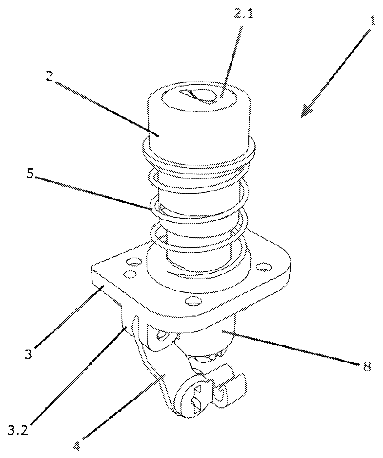
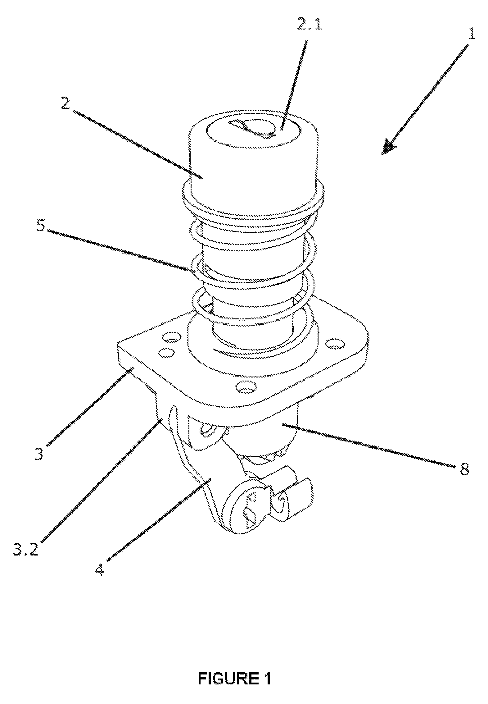
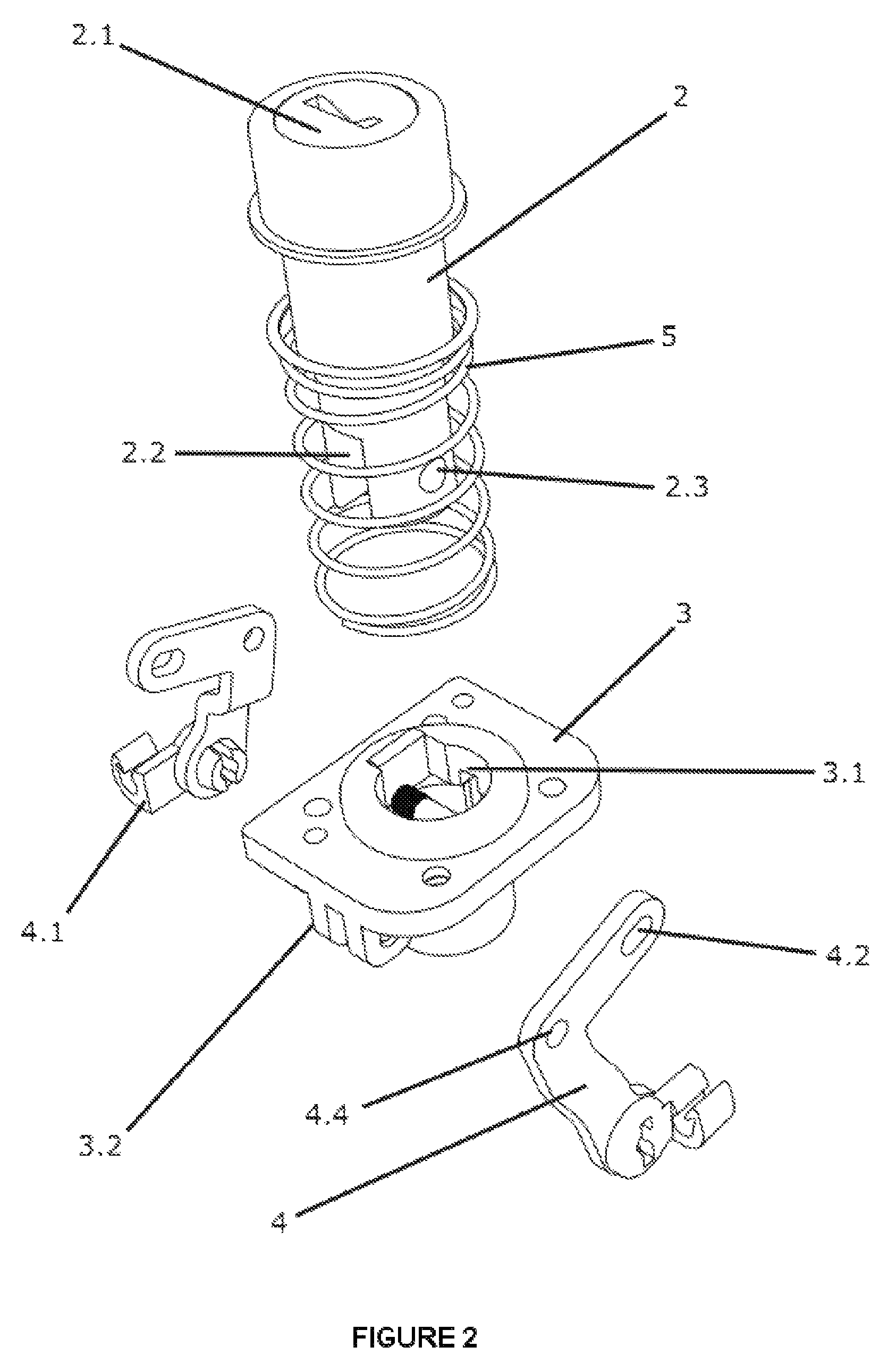
[0029]With reference to FIGS. 1, 2, 3, 4, 5, 6 and 7, it can be noticed that the basic and fundamental version of the locking mechanism, hereafter referenced only as the mechanism (1), is fundamentally composed of a main cylinder (2), a fixed base (3) and articulated arms (4) equipped with rod holders (4.1).

[0030]The main cylinder (2) consists of a cylindrical body, partially tubular, preferably suitable for the optional reception of a core lock (2.1). One end of the main cylinder (2), the opposite end to the end suitable for receiving the core lock, incorporates a diametrically disposed slot, forming two semicircular walls (2.2) which are p...


PUM


Abstract

A locking mechanism (1) responsible for moving crossed rods for locking a door or compartment of a vehicle such as a bus, has a main cylinder (2), a fixed base (3) and articulated arms (4) equipped with rod holders (4.1). The locking mechanism herein being substantially more compact and efficient than similar mechanisms in terms of application and functionality, as the locking mechanism avoids rotating parts in the mechanism for effecting locking and unlocking, instead relying on a push / pull activation which provides many advantages.

Description

TECHNICAL FIELD[0001]The invention relates to a novel locking mechanism, which consists of a locking mechanism responsible for the activation of crossed rods, the whole system, including the mechanism and crossed rods, preferably being used on luggage doors of large vehicles, such as, for example, buses and the like.[0002]The locking mechanism herein disclosed is substantially more compact and efficient, in terms of functionality and implementation, than similar mechanisms belonging to the current state of the art.BACKGROUND ART[0003]The current state of the art consists of a huge range of locking mechanisms, which are intended mainly to enable a mobile wall or door to be securely locked and opened only by authorized persons. Currently existing locking mechanisms are used in distinct and specialized applications, while the principle of operation varies according to the different “groups” of locking mechanisms.[0004]Among the existing locking mechanisms, we highlight the locking mech...

Claims


Application Information

Patent Timeline
Patent Type & Authority Patents(United States)
IPC IPC(8): E05B3/00E05C1/06E05B1/00E05B13/10E05B47/02E05B51/02E05B81/04E05B81/10E05B83/16E05B83/22E05C9/04
CPCE05B83/16E05B81/10E05B1/0038E05C9/046E05B13/105E05B83/22E05B81/04E05B51/02E05B47/02Y10S70/20Y10T70/7757Y10T70/7559Y10T292/57Y10T70/7051Y10T70/7107
Inventor LOPES, ANTONIO, JORGE, FREIRE
Owner SOUTHCO BRASIL COMPONENTES INDIS
Why Eureka
Try Eureka