Fixing mechanism of wire guide of wire electric discharge machine

a technology of fixing mechanism and wire guide, which is applied in the direction of electric circuits, manufacturing tools, instruments, etc., can solve the problems of difficult manufacturing of parts, high cost, and the wire guide is not always restored on the same position, so as to improve the fixing accuracy of the wire guide. , the effect of high productivity

Active Publication Date: 2014-09-16
FANUC LTD
View PDF38 Cites 1 Cited by
  • Summary
  • Abstract
  • Description
  • Claims
  • Application Information

AI Technical Summary

Benefits of technology

[0012]Therefore, in the present invention, it is an object to provide a fixing mechanism of a wire guide of a wire electric discharge machine which exhibits enhanced restoration accuracy of a wire guide fixing position after the wire guide is detached from a wire guide supporting part and has high productivity.
[0019]According to the present invention, a fixing mechanism of a wire guide of a wire electric discharge machine which exhibits enhanced restoration accuracy of a wire guide fixing position after the wire guide is detached from a wire guide supporting part and has high productivity can be provided.

Problems solved by technology

In a case of this configuration, high restoration accuracy of a position in the Z direction which is orthogonal to the XY plane of the abutting faces can be expected, but an error caused by a gap between the male screw and the female screw is generated in the XY direction.
It is difficult to manufacture a part of which fitting accuracy between a male screw and a female screw is enhanced, requiring higher cost.
Consequently, a wire guide is not always restored on the same position when the wire guide is detached and attached again, commonly generating an error of 10 μm or more between before and after detachment of the wire guide from the wire guide supporting part.
Therefore, when a wire guide is exchanged for another wire guide, a previous measurement value which is stored in a control device cannot be used as it is and it is necessary to perform measurement requiring long time in every exchange.
Thus, even though wire guides need to be frequently exchanged depending on a machining content, a fixing mechanism of a wire guide according to prior art has the configuration that requires considerable steps in every exchange of wire guides, deteriorating productivity of a wire electric discharge machine.

Method used


Image

  • Fixing mechanism of wire guide of wire electric discharge machine
  • Fixing mechanism of wire guide of wire electric discharge machine
  • Fixing mechanism of wire guide of wire electric discharge machine

Examples


first embodiment

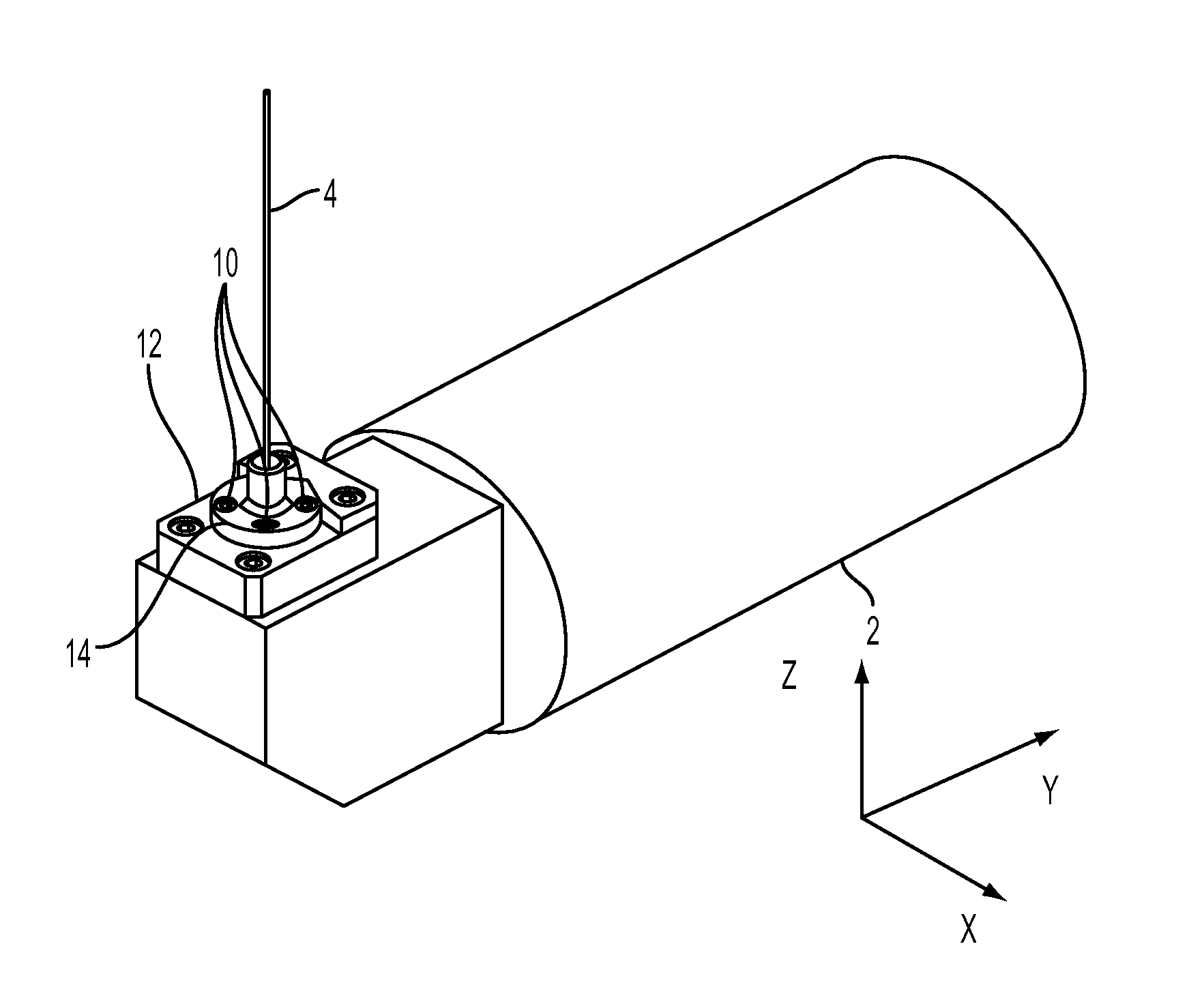
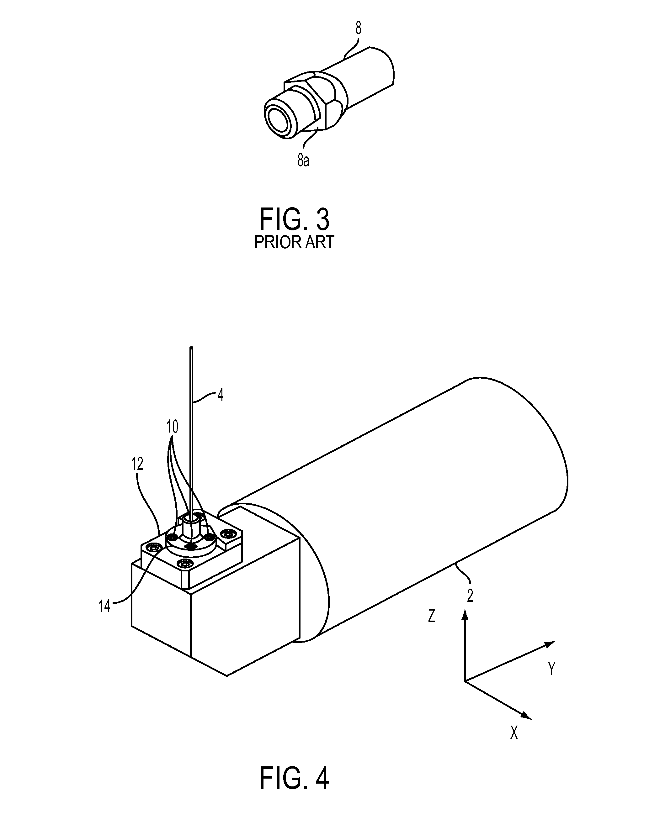
[0048]A fixing mechanism of a wire guide according to the present invention is first described with reference to FIGS. 4 to 6. This embodiment is characterized in that both of a wire guide supporting part and a wire guide have V-shaped planar parts.

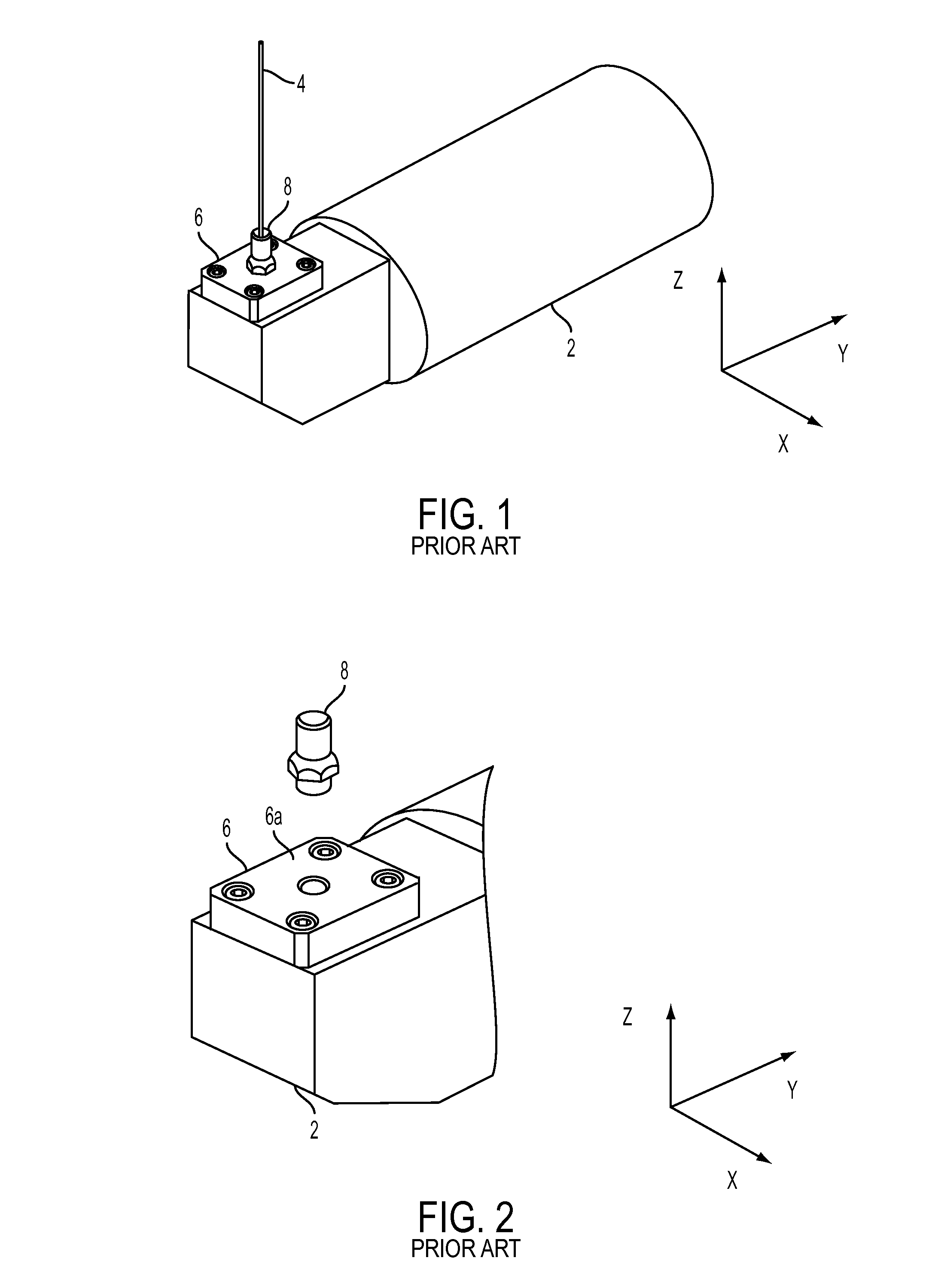
[0049]Commonly, a wire electric discharge machine supports a wire electrode 4 with an upper wire guide and a lower wire guide and relatively moves the wire electrode 4 and a workpiece (not depicted) so as to machine the workpiece. The upper wire guide and the lower wire guide are respectively supported by an upper wire guide supporting part and a lower wire guide supporting part. The upper wire guide and the lower wire guide have the same configuration with respect to one another and the upper wire guide supporting part and the lower wire guide supporting part have the same configuration with one another so as to be collectively called a wire guide and a wire guide supporting part respectively in the description.

[0050]A fixing mechanism f...

second embodiment

[0054]A fixing mechanism of a wire guide according to the present invention is described with reference to FIGS. 7 to 9. This embodiment is characterized in that a wire guide supporting part has two planar parts which are arranged in a V shape, while a wire guide has a single planar part.

[0055]As depicted in FIGS. 7 and 8, a wire guide supporting part 16 has such configuration that two planar parts (orthogonal walls) 16a and 16b are arranged in the V shape on a wire guide supporting face 16c as is the case with the first embodiment (FIGS. 4 and 5). These planar parts 16a and 16b are faces which are different from the wire guide supporting face 16c and are not parallel to each other.

[0056]On the other hand, a single planar part 18b is formed on a wire guide 18 by shaving a part of a cylindrical face 18a of the wire guide 18 as depicted in FIG. 9. When the wire guide 18 is fixed on the wire guide supporting part 16, the cylindrical face 18a of the wire guide 18 is first abutted on the...

third embodiment

[0058]A fixing mechanism of a wire guide according to the present invention is now described with reference to FIGS. 10 to 12. This embodiment is characterized in that a wire guide supporting part has a fitting part having a convex shape, while a wire guide has a fitting part having a concave shape.

[0059]A wire guide supporting part 20 is provided with three convex fitting parts which are fitting convex parts 20a, 20b, and 20c, as depicted in FIG. 11. On the other hand, a wire guide 22 is provided with three concave fitting parts which are fitting concave parts 22a, 22b, and 22c, as depicted in FIG. 12. When the wire guide 22 is fixed on the wire guide supporting part 20 with a fixing means such as the screw 10, the fitting concave parts 22a, 22b, and 22c of the wire guide 22 are first fitted to the fitting convex parts 20a, 20b, and 20c of the wire guide supporting part 20. Then, the wire guide 22 is fixed on the wire guide supporting part 20 with the fixing means such as the screw...


PUM

PropertyMeasurementUnit
diameteraaaaaaaaaa
shapeaaaaaaaaaa
relative rotationaaaaaaaaaa

Abstract

On a wire guide supporting face of a wire guide supporting part which supports a wire guide of a wire electric discharge machine, two wall faces which are orthogonal to the wire guide supporting face are formed to be arranged in a V shape. On the other hand, two planar parts which are abutted on the two orthogonal wall faces, which are arranged in the V shape, of the wire guide supporting part are formed on the wire guide. Then, the wire guide is fixed on the wire guide supporting part with a screw in a state in which the two orthogonal wall faces of the wire guide supporting part and the two planar parts of the wire guide are respectively abutted on each other.

Description

RELATED APPLICATIONS[0001]The present application claims priority from, Japanese Application No. 2012-007448 filed Jan. 17, 2012, the disclosure of which is hereby incorporated by reference herein in its entirety.BACKGROUND OF THE INVENTION[0002]1. Field of the Invention[0003]The present invention relates to a fixing mechanism, which fixes a wire guide on a wire guide supporting face of a wire guide supporting part, of a wire guide of a wire electric discharge machine.[0004]2. Description of the Related Art[0005]In a wire electric discharge machine which stretches a wire electrode in the Z direction and relatively moves the wire electrode and a workpiece so as to machine the workpiece, the wire electrode is restrained by a part which is called a wire guide so as not to move in the XY direction. The wire guide is detachably fixed on a wire guide supporting part by a fixing means such as a screw. The wire guide is commonly formed such that a circular hole which is larger than a diamet...

Claims


Application Information

Patent Timeline
Patent Type & Authority Patents(United States)
IPC IPC(8): B23H7/00B23H7/14G06F19/00B23H1/00B23H7/10
CPCB23H1/00B23H7/105B65H57/12B65H57/26B65H2701/36
Inventor YAMANE, HIKARU
Owner FANUC LTD
Why Eureka
Try Eureka