Battery charging method and system with three-stage temperature-compensated charge profile

a battery and charge profile technology, applied in the field of battery charging, can solve problems such as risk of thermal runaway, and achieve the effect of avoiding excessive water consumption and maximizing the conversion of active materials

Active Publication Date: 2014-09-23
ENERPRO
View PDF12 Cites 5 Cited by
  • Summary
  • Abstract
  • Description
  • Claims
  • Application Information

AI Technical Summary

Benefits of technology

[0017]during a ‘float stage’, provides a constant charge current to the battery of typically 1% of capacity. The battery voltage automatically decreases or increases with temperature to maintain constant float current, effectively producing inherent temperature compensation without the need for a problematic temperature probe.
[0022]The improved charging method is particularly well-suited to use with flooded and valve-regulated lead-acid locomotive batteries that provide a low to moderate current to support critical locomotive functions (computer, radio, lights, etc.) when the engine is stopped, and a high current (1000+ A) to crank the engine. The improved method avoids excessive bulk stage current, provides the manufacturer's recommended absorption stage equalization voltage, and makes the transition to the float stage at a time that maximizes the conversion of active material while avoiding excessive water consumption.

Problems solved by technology

Proper timing of the absorption-to-float stage transition is critical; made too early and the battery is not completely charged, while thermal runaway is risked if made too late.

Method used


Image

  • Battery charging method and system with three-stage temperature-compensated charge profile
  • Battery charging method and system with three-stage temperature-compensated charge profile
  • Battery charging method and system with three-stage temperature-compensated charge profile

Examples


Embodiment Construction

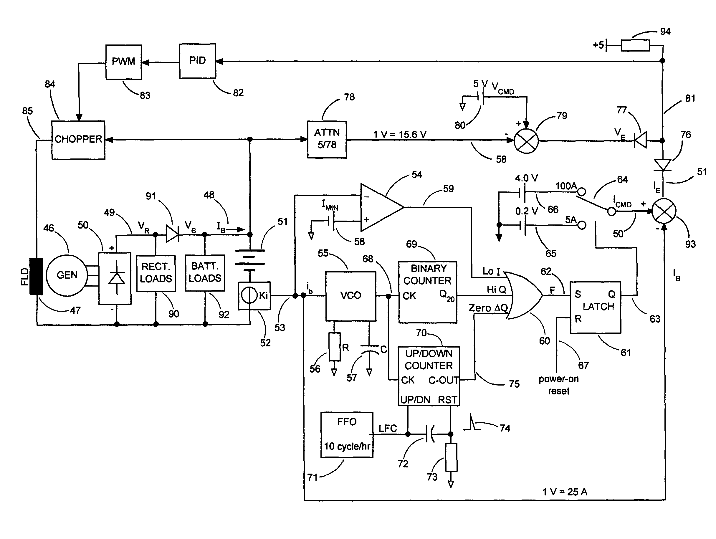
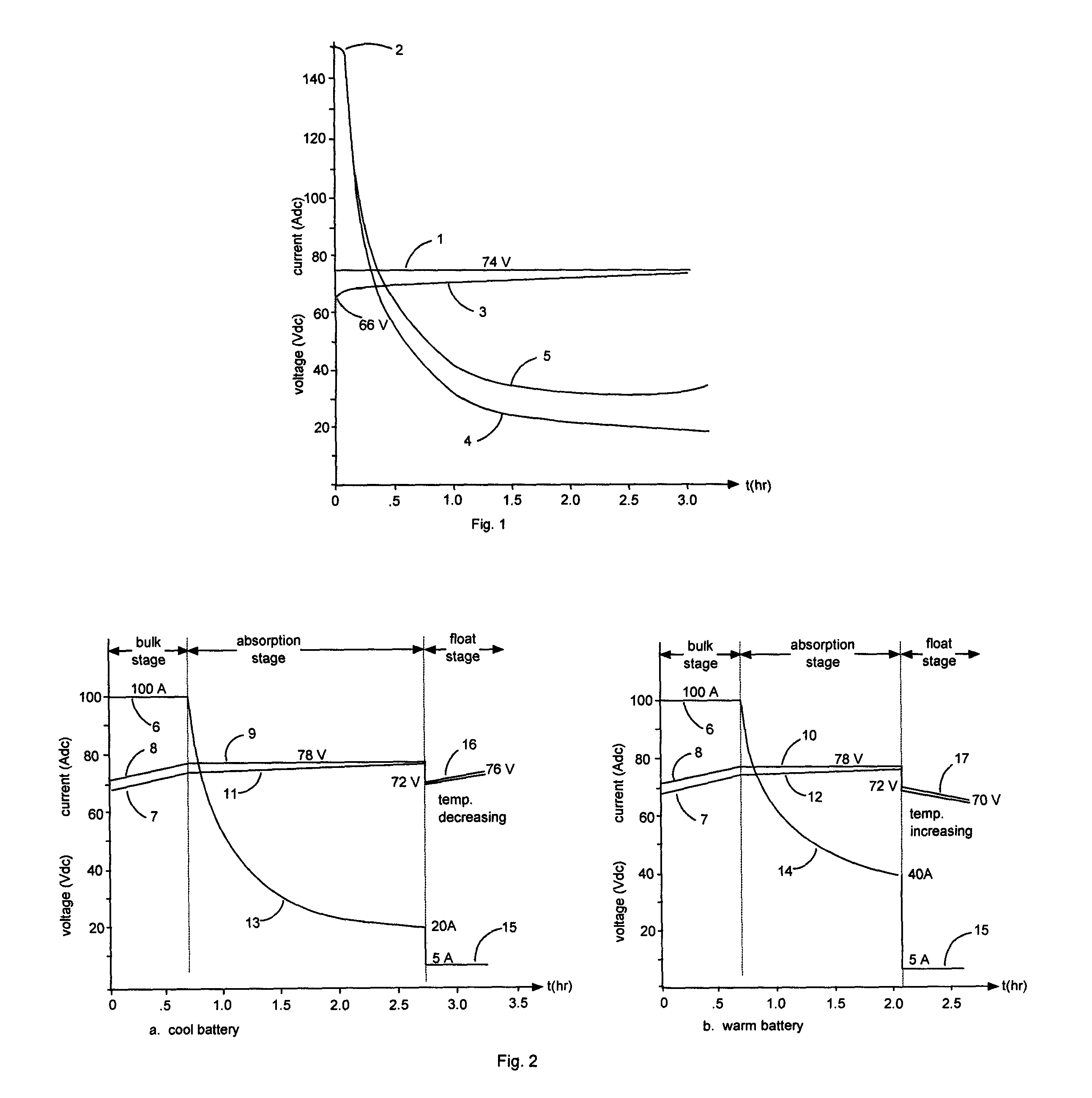
[0028]The present three-stage temperature-compensated charge profile, which is particularly well-suited for use with flooded or valve-regulated lead-acid batteries used in locomotives, is illustrated in FIGS. 2a and 2b, which depict charge voltage vs. time for a cool and a warm battery, respectively. The charge profile progresses through ‘bulk’, ‘absorption’ and ‘float’ stages. During the ‘bulk stage’, the charger regulates the charge current (6) to a predetermined percentage of the battery's amp-hour (A-h) capacity. Note that the various values and percentages provided in the following description and the accompanying figures are merely exemplary. For purposes of illustration, a 500 A-h battery suitable for use in a locomotive is assumed, and the various values and percentages specified in the description and figures are typical for such an application. Note, however, that different values and percentages might be appropriate, depending on the specific battery and application. Also...


PUM


Abstract

A battery charging method and system with a temperature-compensated charge profile requires that, during a ‘bulk stage’, a regulated constant charge current is provided to the battery until the voltage across it increases to a predetermined ‘absorption stage voltage limit’, at which time charging transitions to an ‘absorption stage’. During the absorption stage, a charge current is provided which maintains the voltage across the battery at the absorption stage voltage limit, until: 1) the charge current falls to a predetermined current threshold, 2) the charge delivered to the battery during the absorption stage reaches a predetermined charge threshold, or 3) the difference in charge between two successive intervals of equal duration becomes zero, at which time charging transitions to a ‘float stage’. During the ‘float stage’, a regulated constant charge current is provided, such that the voltage across the battery varies with the temperature of the battery.

Description

BACKGROUND OF THE INVENTION[0001]1. Field of the Invention[0002]This invention relates to the field of battery charging, and particularly to methods and systems for battery charging using a specified charge profile.[0003]2. Description of the Related Art[0004]Rechargeable lead-acid batteries are charged while their DC loads are disconnected, or while their loads are connected. The former would be represented by lift-truck and golf cart batteries, while the latter would include engine-powered road or rail vehicles. Battery chargers provide a current to and a voltage across the battery in accordance with a predetermined ‘charge profile’. Freight and passenger locomotives typically use a 32 cell battery; a generator powered by the traction engine is used to recharge the battery after the engine is started and to keep the battery charged while simultaneously supplying the various DC auxiliary loads (lights, air conditioning, heating, computer, etc.) while the locomotive is in service.[0...

Claims


Application Information

Patent Timeline
Patent Type & Authority Patents(United States)
IPC IPC(8): H02J7/00
CPCH02J7/0091H02J7/0081H02J7/007184H02J7/007194
Inventor BOURBEAU, FRANK J.MATHERLY, JAMES T.
Owner ENERPRO
Why Eureka
Try Eureka