Battery charging method and system with three-stage temperature-compensated charge profile

a battery and charge profile technology, applied in the field of battery charging, can solve the problems of reducing the capacity of the battery to accept charge, affecting the usefulness of using di/dt as a preventer of thermal runaway, and affecting the conversion rate of active materials, so as to avoid excessive water consumption and maximize the effect of active material conversion

Active Publication Date: 2011-06-16
ENERPRO
View PDF11 Cites 17 Cited by
  • Summary
  • Abstract
  • Description
  • Claims
  • Application Information

AI Technical Summary

Benefits of technology

[0020]The improved charging method is particularly well-suited to use with flooded and valve-regulated lead-acid locomotive batteries that provide a low to moderate current to support critical locomotive functions (computer, radio, lights, etc.) when the engine is stopped, and a high current (1000+ ...

Problems solved by technology

If not all the material is converted (lead→lead sulfide), a sulfur compound will build up on the battery's plates, which degrades the battery's ability to accept charge.
However, using di/dt as an Absorption/Float Stage transition criterion can be problematic in the locomotive application, where live DC loads are switched on and off while the locomotive is in service.
Since battery current is highly disturbed for a time after the load transient, the usefulness of using di/dt as a preventer of thermal runaway may be limited.
However, it is doubtful that using battery voltage dv/dt to control the charge profile would be possible if, as in the locomotive application, loads are connected and disconnected while the battery is being charged.
However, locomotive operators have found it problematic to measure the actual battery temperature with a delicate temperature probe in the rugged locomotive environment.
Use of a one-stage charge profile as described above can adversely affect the performance characteristics of a locomotive battery, such as the ability to support lighting and other loads when parked with the engine not running, or the ability to provide adequate (1000+ A) engine cranking current, especially at low ambient temperature.
Locomotiv...

Method used


Image

  • Battery charging method and system with three-stage temperature-compensated charge profile
  • Battery charging method and system with three-stage temperature-compensated charge profile
  • Battery charging method and system with three-stage temperature-compensated charge profile

Examples


Embodiment Construction

rofile as is used on locomotives made by EMD and others.

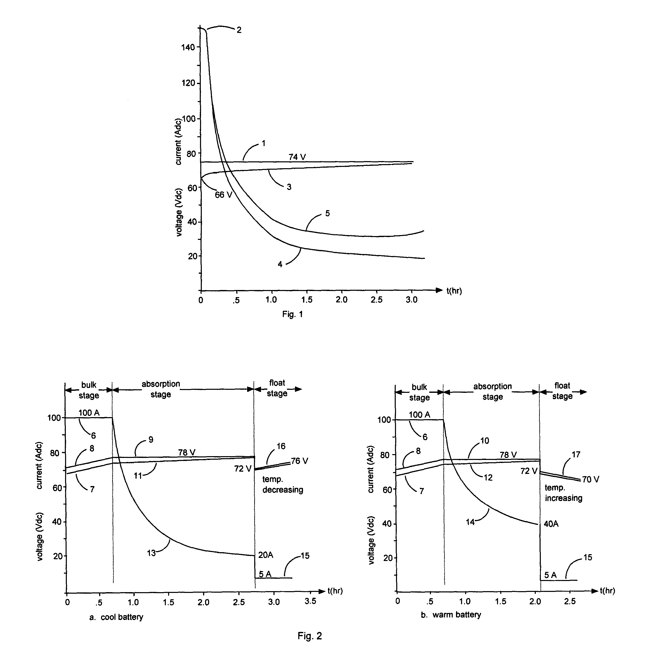
[0023]FIGS. 2a and 2b depict three-stage temperature-compensated charge profiles in accordance with the present invention, for a cool battery and a warm battery, respectively.

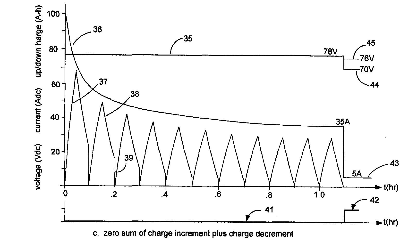
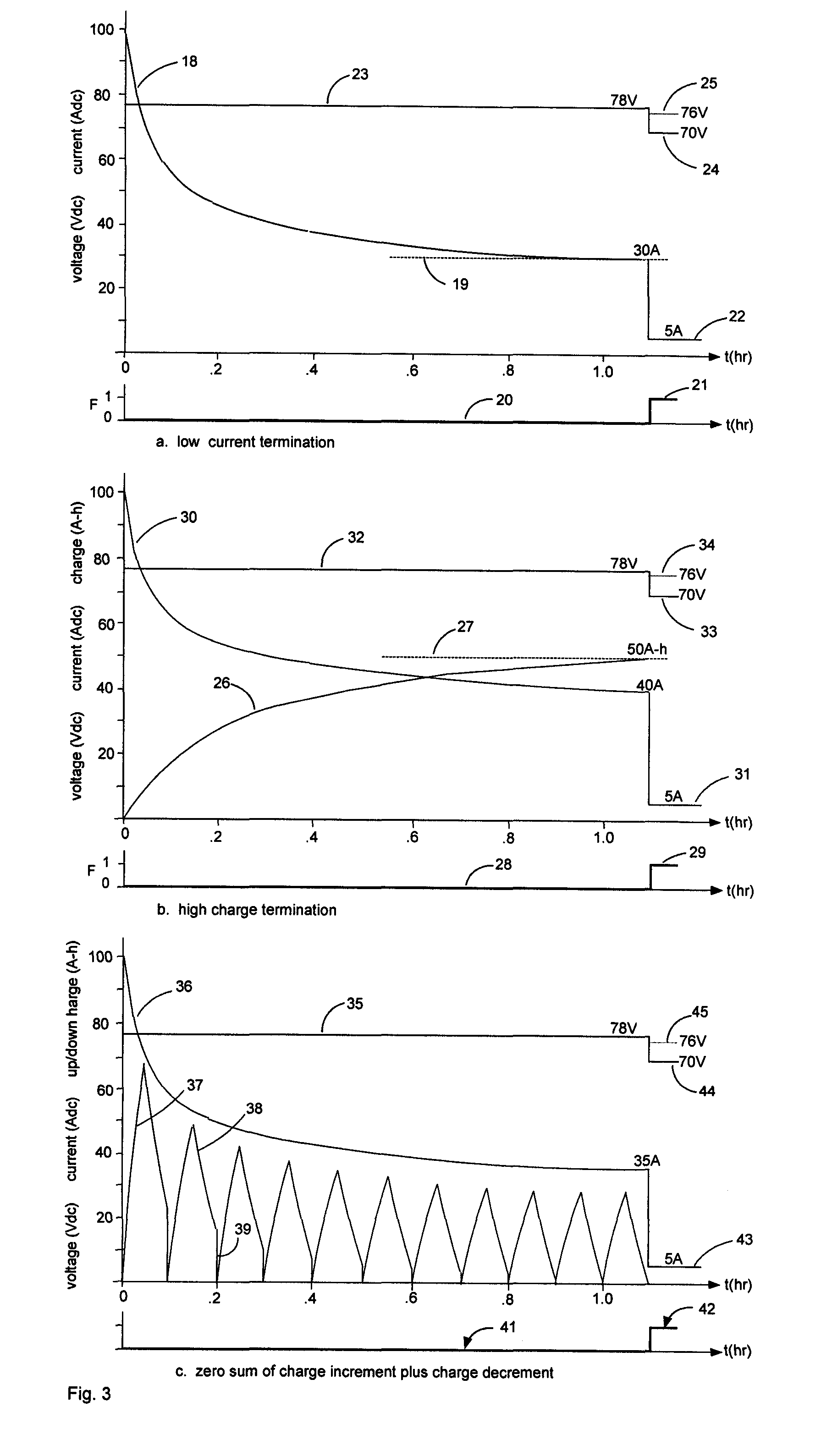
[0024]FIGS. 3a-3c are graphs illustrating the three possible absorption-to-float stage transition mechanisms in accordance with the present invention.

[0025]FIG. 4 is a block diagram of a battery charging system in accordance with the present invention.

DETAILED DESCRIPTION OF THE INVENTION

[0026]The present three-stage temperature-compensated charge profile, which is particularly well-suited for use with flooded or valve-regulated lead-acid batteries used in locomotives, is illustrated in FIGS. 2a and 2b, which depict charge voltage vs. time for a cool and a warm battery, respectively. The charge profile progresses through ‘bulk’, ‘absorption’ and ‘float’ stages. During the ‘bulk stage’, the charger regulates the charge current (6) to a predetermined percent...


PUM


Abstract

A battery charging method and system with a temperature-compensated charge profile requires that, during a ‘bulk stage’, a regulated constant charge current is provided to the battery until the voltage across it increases to a predetermined ‘absorption stage voltage limit’, at which time charging transitions to an ‘absorption stage’. During the absorption stage, a charge current is provided which maintains the voltage across the battery at the absorption stage voltage limit, until: 1) the charge current falls to a predetermined current threshold, 2) the charge delivered to the battery during the absorption stage reaches a predetermined charge threshold, or 3) the difference in charge between two successive intervals of equal duration becomes zero, at which time charging transitions to a ‘float stage’. During the ‘float stage’, a regulated constant charge current is provided, such that the voltage across the battery varies with the temperature of the battery.

Description

BACKGROUND OF THE INVENTION[0001]1. Field of the Invention[0002]This invention relates to the field of battery charging, and particularly to methods and systems for battery charging using a specified charge profile.[0003]2. Description of the Related Art[0004]Rechargeable lead-acid batteries are charged while their DC loads are disconnected, or while their loads are connected. The former would be represented by lift-truck and golf cart batteries, while the latter would include engine-powered road or rail vehicles. Battery chargers provide a current to and a voltage across the battery in accordance with a predetermined ‘charge profile’. Freight and passenger locomotives typically use a 32 cell battery; a generator powered by the traction engine is used to recharge the battery after the engine is started and to keep the battery charged while simultaneously supplying the various DC auxiliary loads (lights, air conditioning, heating, computer, etc.) while the locomotive is in service.[0...

Claims


Application Information

Patent Timeline
IPC IPC(8): H02J7/04
CPCH02J7/0091H02J7/0081H02J7/007184H02J7/007194
Inventor BOURBEAU, FRANK J.MATHERLY, JAMES T.
Owner ENERPRO
Why Eureka
Try Eureka