
Systems and methods of achieving high brightness infrared fiber parametric amplifiers and light sources

a parametric amplifier and infrared fiber technology, applied in the field of optical communication networks, can solve the problems of increased nonlinearities in the fiber, low power emitters, and inability to achieve parametric amplification in the mid ir wavelength, and achieve the effect of reducing power penalties

Active Publication Date: 2015-08-04
US GOVT REPRESENTED BY THE SEC OF THE NAVY CHIEF OF NAVAL RES ONR NRL
View PDF10 Cites 3 Cited by
  • Summary
  • Abstract
  • Description
  • Claims
  • Application Information

AI Technical Summary

Benefits of technology

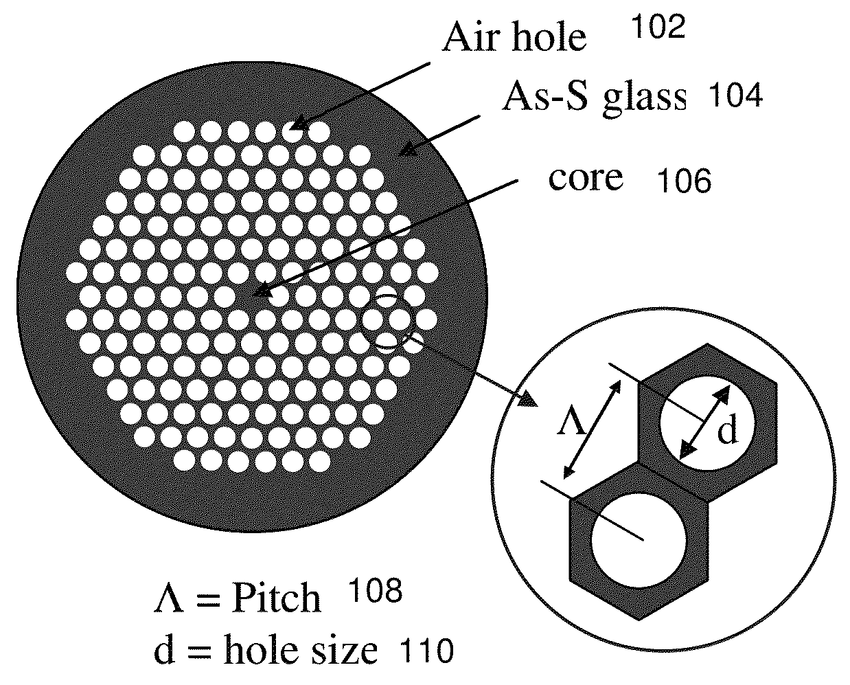
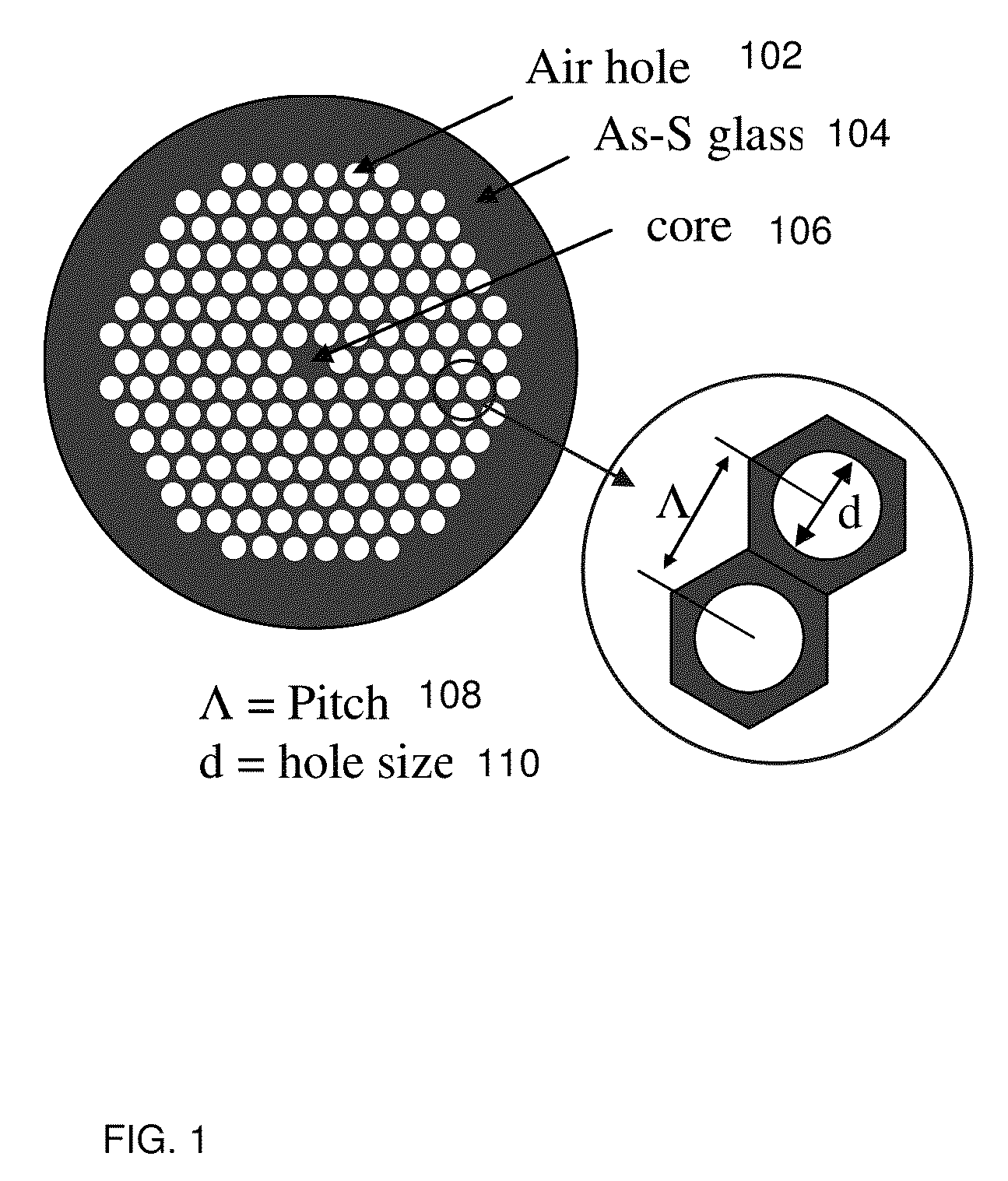
The patent describes a way to create a fiber structure that amplifies infrared light using a special type of fiber made from chalcogenide. The fiber has holes and a certain pitch pattern that can be controlled during fabrication and through use with pump and signal waves. As a result, the fiber can efficiently convert laser light into different forms with low power. The design also minimizes power penalties and noise.

Problems solved by technology

Parametric amplification has been demonstrated in media of varying compositions, such as silica fiber at near IR wavelengths and visible light wavelengths; however, parametric amplification has not been achieved in the mid IR wavelengths.
In photonic crystal fiber, very small core sizes are obtainable, resulting in increased nonlinearities in the fiber.
IR Blackbody sources are highly broadband, but are very low power emitters.
Optical Parametric Oscillator (OPO) sources, IR diode lasers, gas lasers, and IR solid sate lasers are complex, bulky, and expensive.

Method used


Image

  • Systems and methods of achieving high brightness infrared fiber parametric amplifiers and light sources
  • Systems and methods of achieving high brightness infrared fiber parametric amplifiers and light sources
  • Systems and methods of achieving high brightness infrared fiber parametric amplifiers and light sources

Examples


Embodiment Construction

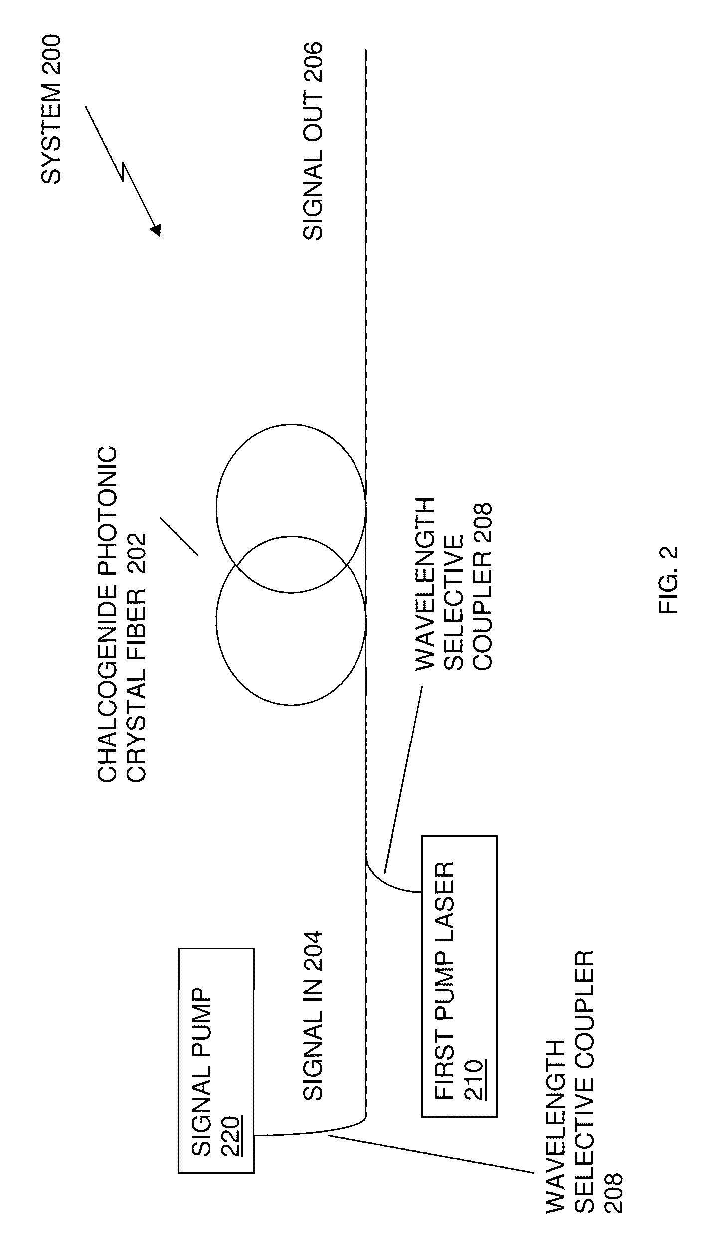
[0021]Preferred exemplary embodiments of the present invention are now described with reference to the figures, in which like reference numerals are generally used to indicate identical or functionally similar elements. While specific details of the preferred exemplary embodiments are discussed, it should be understood that this is done for illustrative purposes only. A person skilled in the relevant art will recognize that other configurations and arrangements can be used without departing from the spirit and scope of the preferred exemplary embodiments. It will also be apparent to a person skilled in the relevant art that this invention can also be employed in other applications. Further, the terms “a”, “an”, “first”, “second” and “third” etc. used herein do not denote limitations of quantity, but rather denote the presence of one or more of the referenced items(s).

[0022]Referring to FIG. 1, FIG. 2, FIG. 3, FIG. 6, FIG. 9A, FIG. 9B and FIG. 9C, in accordance with exemplary embodim...


PUM


Abstract

Fiber optic amplification in a spectrum of infrared electromagnetic radiation is achieved by creating a chalcogenide photonic crystal fiber (PCF) structure having a radially varying pitch. A chalcogenide PCF system can be tuned during fabrication of the chalcogenide PCF structure, by controlling, the size of the core, the size of the cladding, and the hole size to pitch ratio of the chalcogenide PCF structure and tuned during exercising of the chalcogenide PCF system with pump laser and signal waves, by changing the wavelength of either the pump laser wave or the signal wave, maximization of nonlinear conversion of the chalcogenide PCF, efficient parametric conversion with low peak power pulses of continuous wave laser sources, and minimization of power penalties and minimization of the need for amplification and regeneration of pulse transmissions over the length of the fiber, based on a dispersion factor.

Description

CROSS REFERENCE TO RELATED APPLICATIONS[0001]The present application is a nonprovisional application related to provisional application No. 60 / 745,210 under 35 USC 119(e), the entire disclosure of which is incorporated by reference herein.FIELD OF THE INVENTION[0002]The present invention relates generally to optical communications networks, and more particularly to obtaining efficient tunable infrared light (IR) sources comprising optical fiber amplifiers for achieving high brightness IR sources.BACKGROUND OF THE INVENTION[0003]Parametric amplification in a glass optical fiber is a third order nonlinear process dependent upon χ(3) third order nonlinearity properties of the glass. Parametric amplification operates by the process of four wave mixing involving the interaction of four optical waves. In parametric amplification processes, one and / or two laser pump and / or signal pump waves pumped at frequencies ω1 and / or ω2 amplify a signal wave at a frequency ω3 and generate an idler wav...

Claims


Application Information

Patent Timeline
Patent Type & Authority Patents(United States)
IPC IPC(8): H01S3/067G02B6/02H01S3/094H01S3/108H01S3/17
CPCH01S3/06754H01S3/06741H01S3/094096H01S3/1083H01S3/171G02B6/02357G02B6/02342G02B6/02295G02B6/02347
Inventor SHAW, LESLIE BRANDONAGGARWAL, ISHWAR DAYALSANGHERA, JASBINDER SINGHGIBSON, DANIEL JOSEPHKUNG, FREDERIC HAU
Owner US GOVT REPRESENTED BY THE SEC OF THE NAVY CHIEF OF NAVAL RES ONR NRL
Learn More