Dynamic RF matrix emulator

a matrix emulator and dynamic technology, applied in the direction of radio transmission, transmission monitoring, electrical equipment, etc., can solve the problems of rf emulators that cannot support rf switching between a very limited number of terminals, a large challenge in testing wireless networks or devices containing many rf terminals, and a very high cos

Active Publication Date: 2014-09-23
AUTOTALKS
View PDF5 Cites 8 Cited by
  • Summary
  • Abstract
  • Description
  • Claims
  • Application Information

AI Technical Summary

Problems solved by technology

The task of testing wireless networks or devices containing many RF terminals (“terminals”) imposes great challenges.
In the case of mobile terminals (for example installed in vehicles) where communication channels experience temporally and spatially changing environments, such testing becomes even more challenging.
RF emulators can support, at very high cost, RF switching between a very limited number of terminals, but cannot provide full matrix switching for large numbers of terminals.
There is no RF-based implementation (RF channel based testing) that can come even close to emulate such large networks.

Method used


Image

  • Dynamic RF matrix emulator
  • Dynamic RF matrix emulator
  • Dynamic RF matrix emulator

Examples


examples

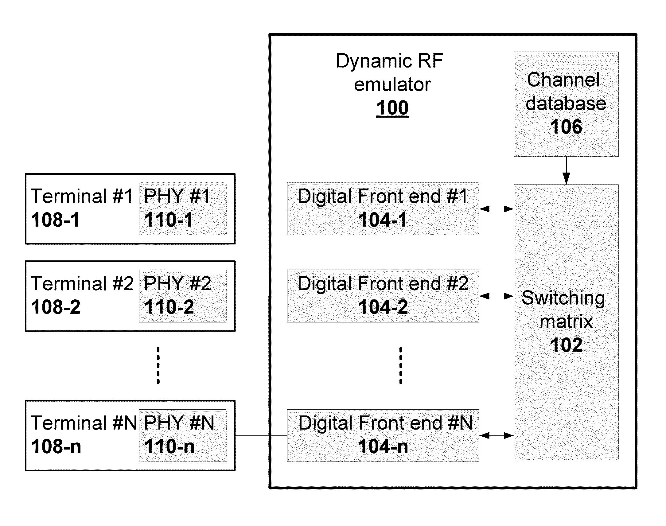
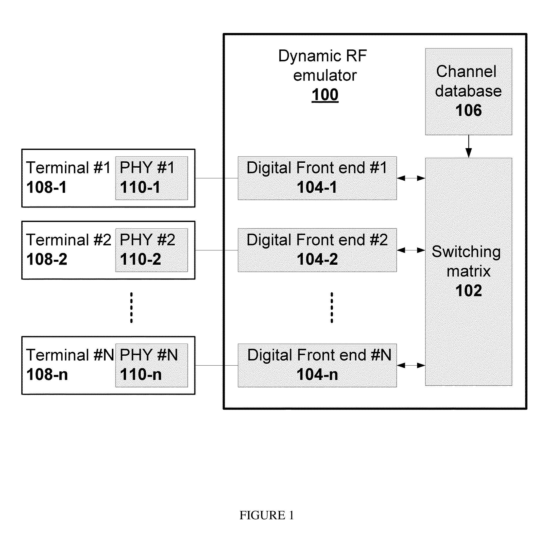
[0056]An example for a switching decision is provided for a single output and for just 16 inputs. The full matrix repeats this calculation for all outputs and hundreds on inputs. The attenuation vector (database entry for an output selector) is as follows: {Open, 8 dB, 16 dB, 16 dB, 8 dB, Open, Open, Open, 32 dB, 32 dB, 8 dB, Open, Open, 24 dB, Open, Open}.

[0057]Assume that the list of the current state of all transmitters, decided in an arbitrary fashion based on current transmissions of terminals using a procedure as in FIG. 5 step 500, is {10 dBm, No, No, No, No, No, 20 dBm, No, No, 10 dBm, No, No, No, No, No, No}. The listed values indicate transmitter power. In this list, there are 3 active transmitters (#1, 7 and 10). Of these, the channels of 1st and 7th transmitters are open and not impacting. Therefore, the 10th transmitter is the only one considered and transmitted as is if its power is higher than the SNR.

[0058]If the 4th input suddenly starts to transmit using 10 dBm out...


PUM


Abstract

A dynamic RF matrix emulator uses digital switching to emulate the switching behavior of hundreds of wireless terminals. The emulator includes a switching matrix with channels formed between terminal pairs, digital front ends for coupling terminals digitally to the switching matrix, and a channel database having entries representing attenuation values which can be changed in time, the attenuation values correlated with movement of vehicles provided by a traffic simulator. Channel behavior is defined by temporal attenuation values obtained from the database. The digital switching is controlled through a digital communication protocol.

Description

CROSS REFERENCE TO RELATED APPLICATIONS[0001]This invention claims priority from U.S. Provisional Patent Application No. 61 / 152,272 filed 13 Feb. 2009, the content of which is incorporated herein by reference.FIELD OF THE INVENTION[0002]The invention disclosed herein relates in general to testing of wireless networks or devices and more specifically to systems and methods for emulating wireless networks with large numbers of radio frequency (RF) units (also referred to as “RF terminals”).BACKGROUND OF THE INVENTION[0003]The task of testing wireless networks or devices containing many RF terminals (“terminals”) imposes great challenges. Any two terminals can communicate through a wireless communication channel. As opposed to cellular phone testing, in which the communication is limited between a terminal and a centralized base-station, the requirement here is for full switching between all terminals. In the case of mobile terminals (for example installed in vehicles) where communicat...

Claims


Application Information

Patent Timeline
Patent Type & Authority Patents(United States)
IPC IPC(8): H04B17/00
CPCH04B17/009H04B17/391
Inventor HARAN, ONN
Owner AUTOTALKS
Why Eureka
Try Eureka