
Systems and methods for early detection of lead breaches using cross-lead impedances detected by an implantable medical device

a technology of cross-lead impedance and lead impedance, which is applied in the direction of therapy, heart stimulator, heart defibrillator, etc., can solve the problems of exposing the ring conductor to patient tissues, affecting the treatment effect, and affecting the patient's comfor

Active Publication Date: 2014-10-07
PACESETTER INC
View PDF14 Cites 0 Cited by
  • Summary
  • Abstract
  • Description
  • Claims
  • Application Information

AI Technical Summary

Problems solved by technology

However problems can arise if an insulation breach occurs in the lead, potentially exposing one of its internal conducting wires to blood or other patient tissues, yielding a form of short circuit that interferes with the capability of the lead to properly sense cardiac signals and delivery appropriate therapeutic pulses, as well as resulting false sensing leading to impropriate therapy.
In use, however, the sheath can abrade, eventually exposing the ring conductor to patient tissues.
Similar problems can occur in “flat wire” leads as well.
Abrasion or other lead failures can cause: impropriate therapy due to false over-sensing; withheld therapy due to under-sensing or over-sensing (inhibition); failure to deliver therapy due to due to conductor failures; damage to the device itself, etc.
Although lead reliability has improved dramatically over the years, leads can still fail for various reasons.
If the bipolar impedance drifts out of range or fluctuates more than expected, such indicates the lead may be experiencing a fracture.
However, this technique may not be sensitive enough for early detection of lead integrity issues arising due to insulation breach because the impedance change may still be relatively small.

Method used


Image

  • Systems and methods for early detection of lead breaches using cross-lead impedances detected by an implantable medical device
  • Systems and methods for early detection of lead breaches using cross-lead impedances detected by an implantable medical device
  • Systems and methods for early detection of lead breaches using cross-lead impedances detected by an implantable medical device

Examples


Embodiment Construction

[0016]The following description includes the best mode presently contemplated for practicing the invention. This description is not to be taken in a limiting sense but is made merely to describe general principles of the invention. The scope of the invention should be ascertained with reference to the issued claims. In the description of the invention that follows, like numerals or reference designators will be used to refer to like parts or elements throughout.

Overview of Implantable Medical System

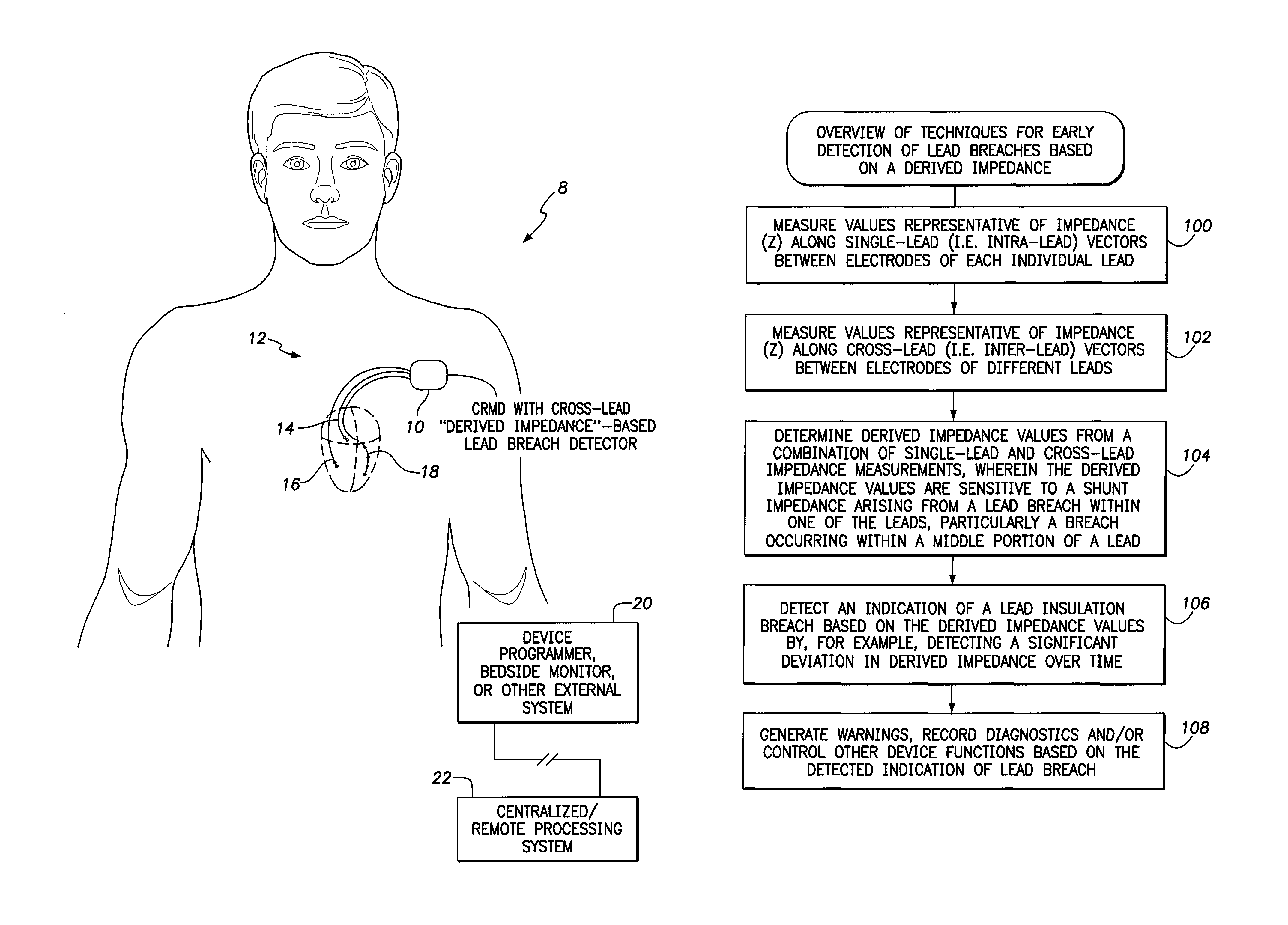
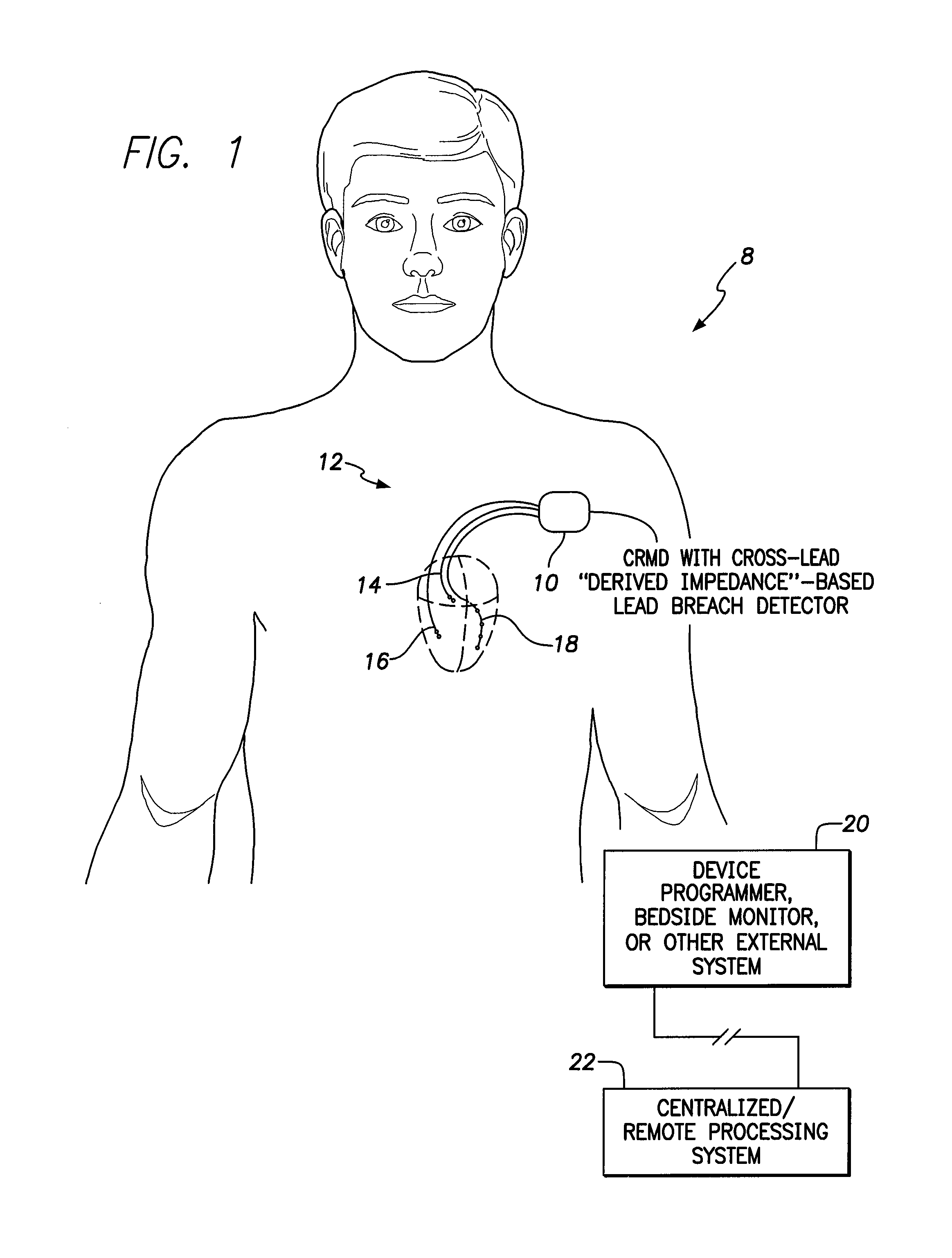
[0017]FIG. 1 illustrates an implantable medical system 8 capable of early detection of a lead breach based on derived impedance values obtained, at least in part, from cross-lead impedance measurements. That is, the CRMD is equipped with a cross-lead “derived impedance”-based lead breach detector. In the particular example of FIG. 1, implantable system 8 includes a CRMD 10 equipped with a set of leads 12 implanted on or within the heart of the patient, including a bipolar RA lead 14, a bi...


PUM


Abstract

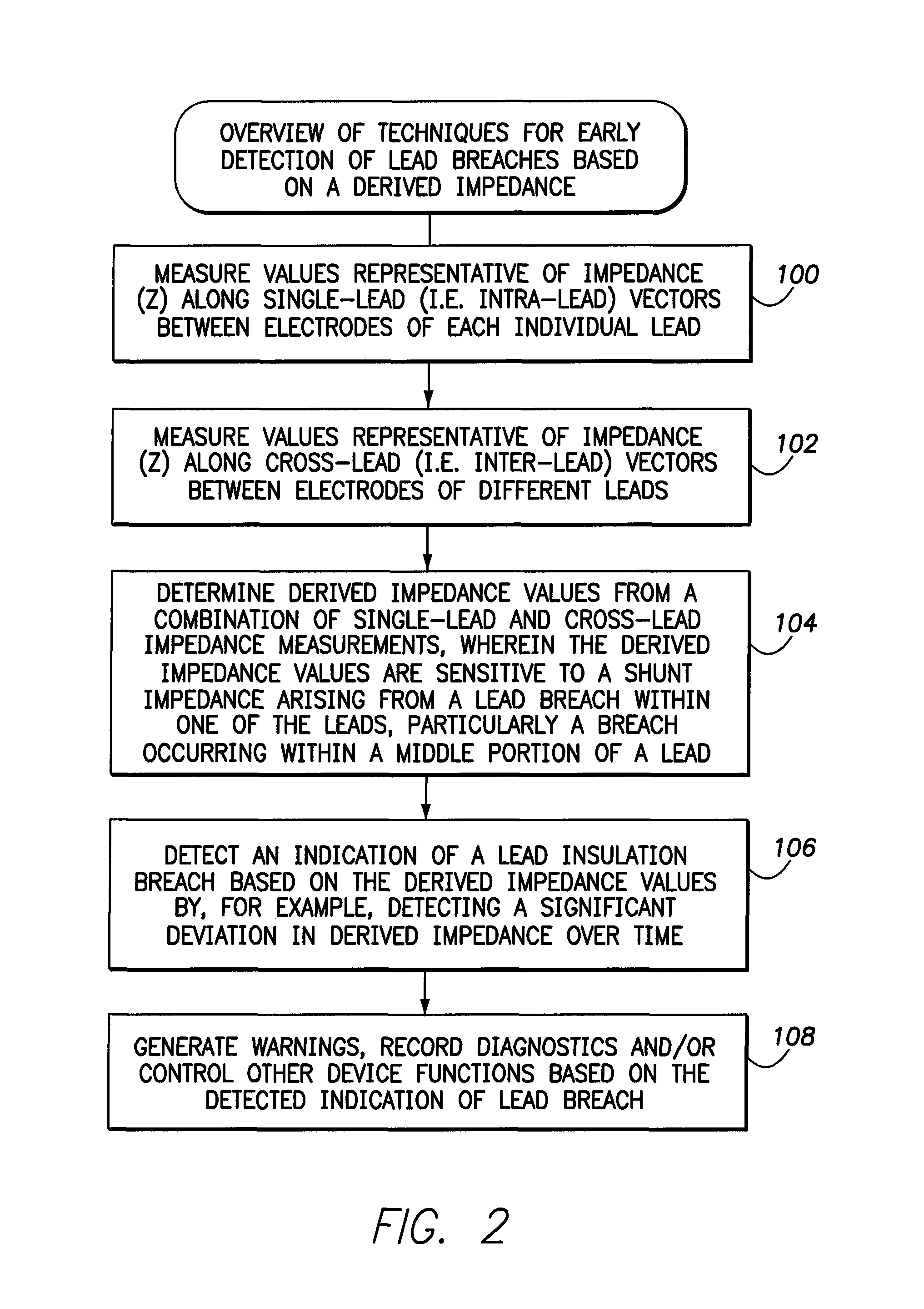
Techniques are provided for use with an implantable medical device for detecting breaches in lead insulation or other lead failures. In one example, bipolar impedance is measured along single-lead vectors (i.e. intra-lead vectors) of a right atrial (RA) lead and a right ventricular (RV) leads. Impedance is also measured along various cross-lead vectors (i.e. inter-lead vectors) between electrodes of the two leads. A derived impedance value is then determined from a combination of the measured impedance values, wherein the derived impedance is sensitive to a shunt impedance arising from a breach within the RV lead. A lead breach is then detected relatively early based on the derived impedance by detecting a significant deviation in derived impedance over time. Unipolar impedance measurements are used to confirm the breach.

Description

FIELD OF THE INVENTION[0001]The invention generally relates to Implantable Cardiac Rhythm Management Devices (CRMDs) and, in particular, to techniques for detecting insulation breaches within leads connected to the devices.BACKGROUND OF THE INVENTION[0002]A wide range of implantable medical devices are provided for surgical implantation within patients, such as cardiac pacemakers, implantable cardioverter defibrillators (ICDs), cardiac resynchronization therapy (CRT) devices or other implantable cardiac rhythm management devices (CRMDs.) Typically, such devices are equipped with one more leads for sensing electrical signals such as cardiac signals. However problems can arise if an insulation breach occurs in the lead, potentially exposing one of its internal conducting wires to blood or other patient tissues, yielding a form of short circuit that interferes with the capability of the lead to properly sense cardiac signals and delivery appropriate therapeutic pulses, as well as resul...

Claims


Application Information

Patent Timeline
Patent Type & Authority Patents(United States)
IPC IPC(8): A61N1/08A61N1/362A61N1/39
CPCA61N1/3937A61N1/3622A61N1/37A61N2001/083
Inventor PEI, XING
Owner PACESETTER INC
Learn More