capacitor device

A capacitor and capacitor plate technology, applied in the direction of capacitors, multiple fixed capacitors, fixed capacitor terminals, etc., can solve problems such as damage to, hindering the power improvement of electric drive parts of motor vehicles, and aging of capacitor plate stacks.

Active Publication Date: 2018-02-09
VALEO EAUTOMOTIVE GERMANY GMBH
View PDF3 Cites 0 Cited by
  • Summary
  • Abstract
  • Description
  • Claims
  • Application Information

AI Technical Summary

Problems solved by technology

Different capacitor stacks with different loads can lead to premature aging or even damage to the most loaded capacitor stack
In practice, this hinders the power increase of the electric drive of the motor vehicle to a large extent

Method used


Image

  • capacitor device
  • capacitor device
  • capacitor device

Examples


Embodiment Construction

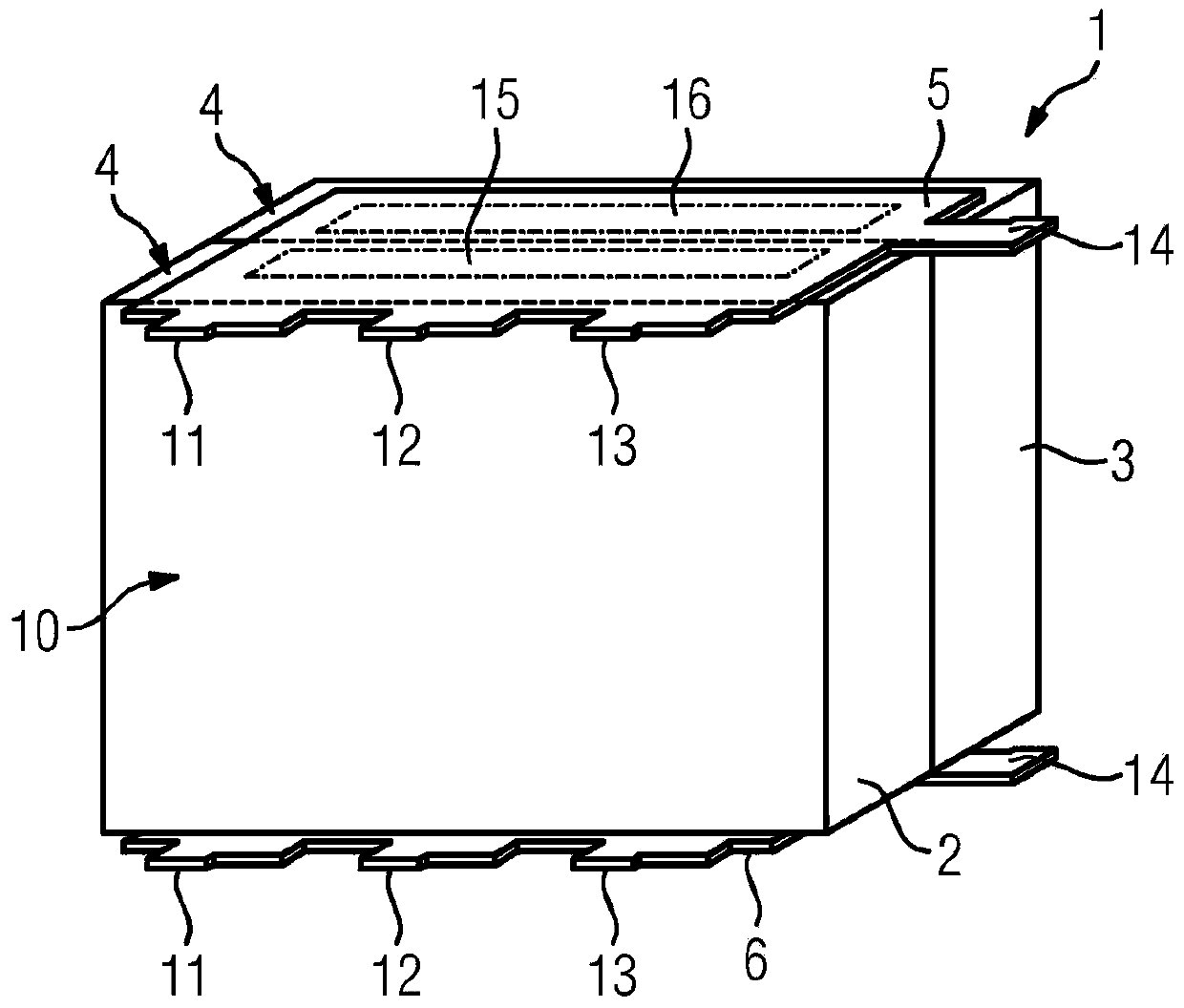
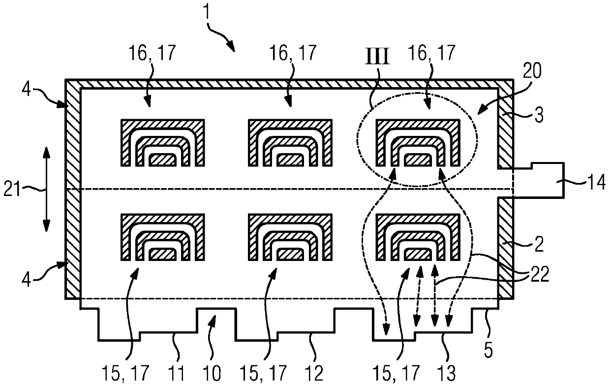
[0033] figure 1 A capacitor arrangement 1 for a (direct current) intermediate circuit of a pulse converter in a drive train of an electric vehicle is shown.

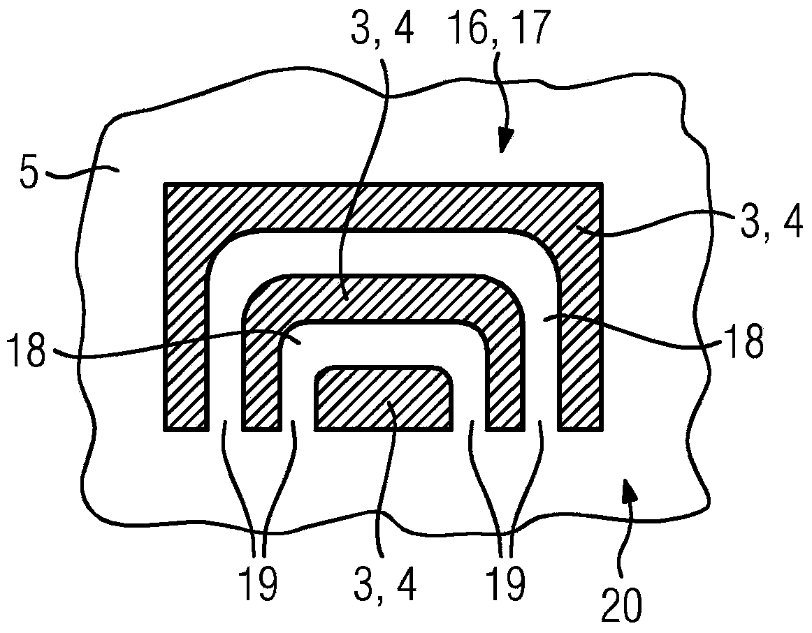
[0034] The capacitor arrangement 1 comprises two capacitor plate stacks 2 and 3 . Capacitor plate stacks 2 and 3 are each a film capacitor, which is conventional per se. Each capacitor plate stack 2 and 3 is formed accordingly from a roll of metallized plastic film, wherein this roll is on both end sides (in accordance with figure 1 are located above and below in the illustration) are metallized to form the connecting surface (hereinafter referred to as Schoob surface (Schoob-Flaechen) 4 ).

[0035] The capacitor arrangement 1 also comprises two busbars for connection to the intermediate circuit, namely a busbar 5 on the high potential side (positive busbar) and a busbar 6 on the low potential side (negative busbar). Each busbar 5 , 6 is formed in each case from a stamped part made of tin-plated copper sheet.

[0036...


PUM


Abstract

The present invention relates to a capacitor device (1) used for an intermediate loop of a pulse transverter, especially used for a driving system of an electric vehicle. The capacitor device (1) comprises at least two capacitor sheet packs (2, 3) which are separated with each other, at least one busbar (5, 6) possessing at least one semiconductor joint (11-13) and at least two contact structures (15, 16) used for contacting the capacitor sheet packs (2, 3) respectively. The contact structures (15, 16) are arranged oppositely and at the different distances relative to the semiconductor joints (11-13), thereby forming the contact structure (15) close to the joint and the contact structure (16) far away from the joint. In order to improve the load capacity of the capacitor device (1) with a simple device, the contact structure (15) close to the joint and the contact structure (16) far away from the joint are constructed differently for at least partially adapting to the corresponding contact structures (15, 16) and the lead impedance between the semiconductor joints (11-13).

Description

technical field [0001] The invention relates to a capacitor arrangement for an intermediate circuit of a pulse converter, in particular for use in a drive train of an electric vehicle. Background technique [0002] The (electric) drive train of an electric vehicle usually consists of a high-voltage battery, a pulse converter connected downstream of the high-voltage battery, and the electric drive motor of the electric vehicle. [0003] The pulse converter is connected via an intermediate circuit (of DC voltage) to the high-voltage battery, which feeds the intermediate circuit with a voltage of usually approximately 400 VDC. A pulse converter (PWR) converts the DC voltage into a usually polyphase AC voltage, which is supplied to the drive motor as drive voltage. As a buffer against brief power fluctuations, an intermediate circuit capacitor is usually inserted in the intermediate circuit. [0004] As an intermediate circuit capacitor, capacitor arrangements are usually used...

Claims


Application Information

Patent Timeline
Patent Type & Authority Patents(China)
IPC IPC(8): H02M1/00H01G4/228H01G4/38
CPCH01G2/04H01G4/228H01G4/40H02M7/003Y02T10/70
Inventor 斯特凡·内图席尔里卡尔多·拉明吉多·舒费特
Owner VALEO EAUTOMOTIVE GERMANY GMBH
Why Eureka
Try Eureka