

Indexable circular cutting insert
a circular cutting insert and indexing technology, applied in the field of cutting inserts, can solve the problems of degrading not only the cutting edge, but the material in the cutting edge region
- Summary
- Abstract
- Description
- Claims
- Application Information
AI Technical Summary
Benefits of technology
Problems solved by technology
Method used
Image

Examples
Embodiment Construction
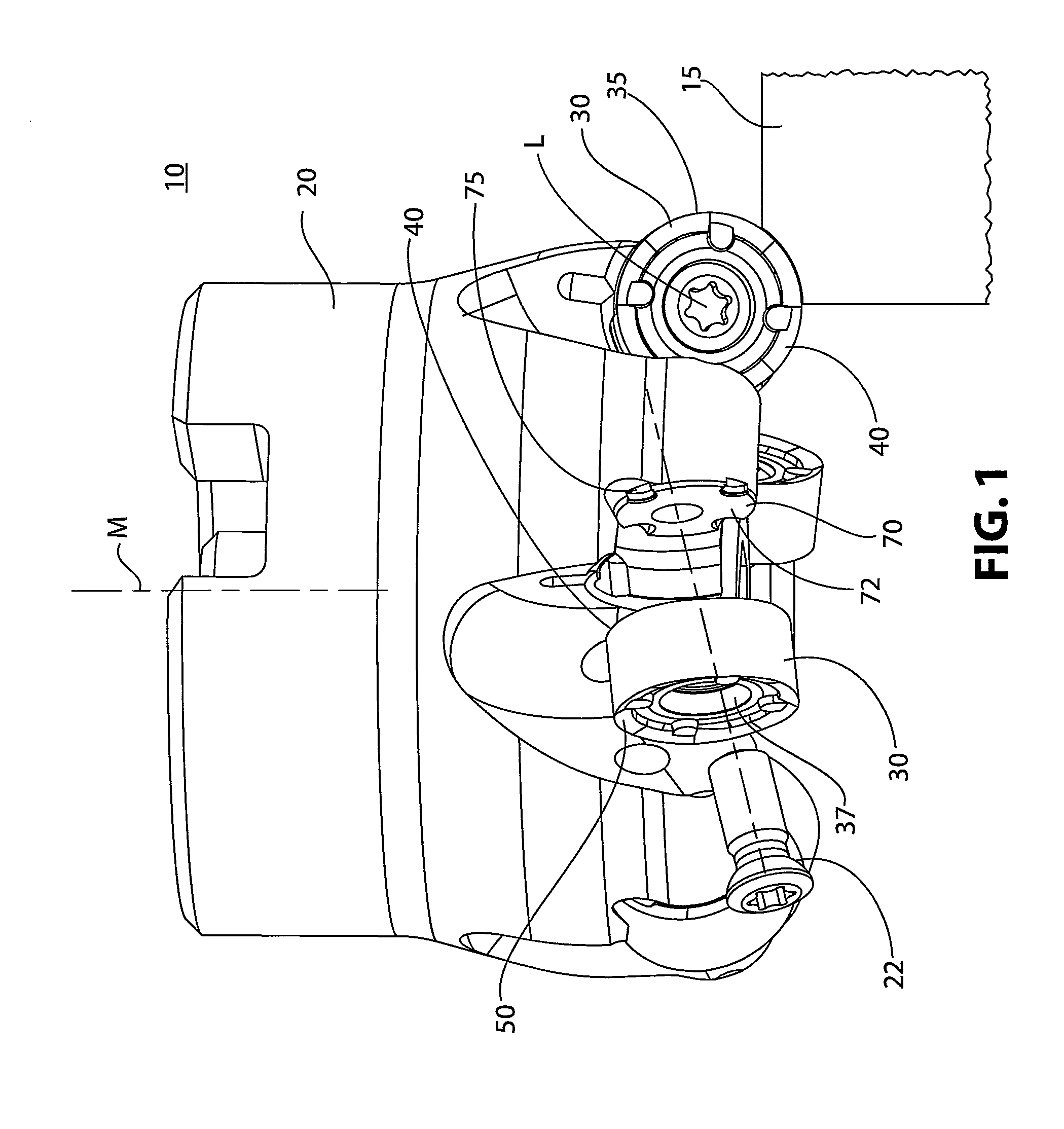
[0020]FIG. 1 illustrates a toolholder system 10 for cutting a workpiece 15, wherein there is relative rotation between a toolholder 20 and the workpiece 15. The toolholder system 10 is comprised of at least one cutting insert 30 and the toolholder 20. The toolholder 20 illustrated in FIG. 1 is a milling cutter that rotates about axis M.
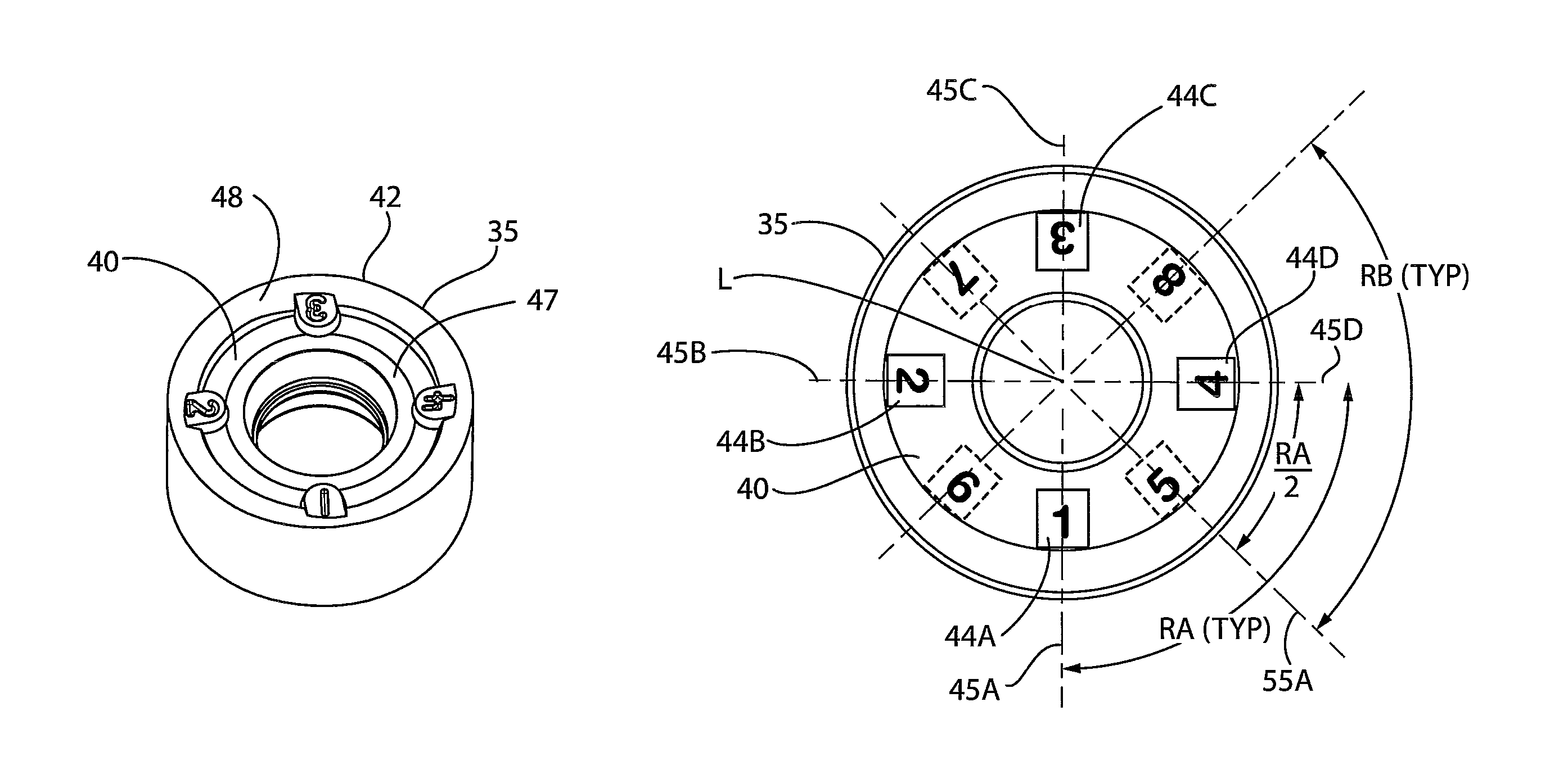
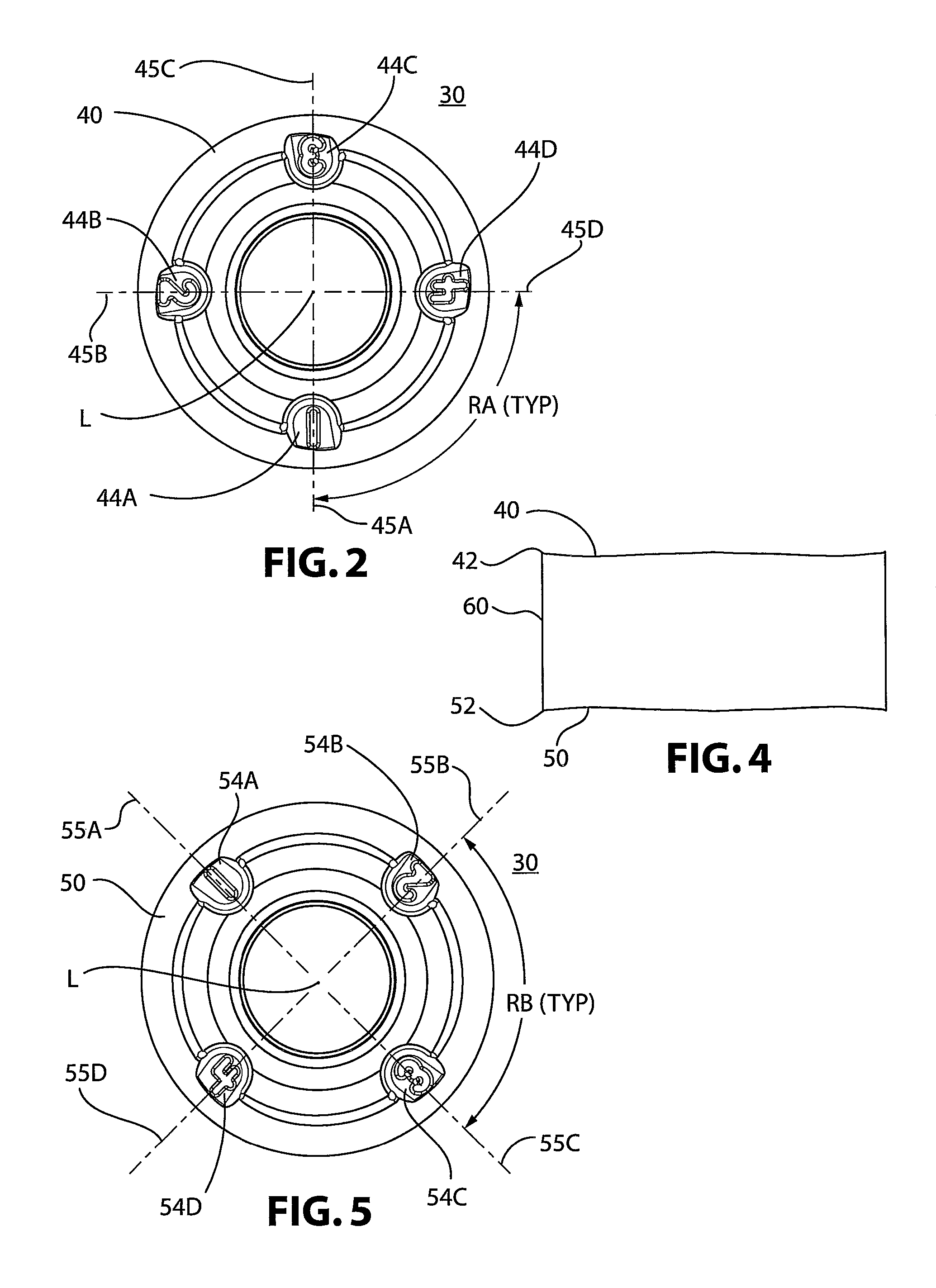
[0021]Directing attention to FIGS. 2-6, the cutting insert 30 has a body 35 with a front face 40, an opposing back face 50, and a side wall 60 therebetween. At the intersection of the sidewall 60 and the front face 40 is a front cutting edge 42. At the intersection of the sidewall 60 and the back face 50 is a back cutting edge 52. A plurality of positioning segments 44A-D, on the front face 40, have radial centerlines 45A-D extending from the longitudinal axis L, wherein the centerlines 45A-D of adjacent segments 44A-D define evenly-spaced radial angles RA about the central longitudinal axis L for indexing the cutting insert 30 within the toolholder 2...
PUM
| Property | Measurement | Unit |
|---|---|---|
| angle | aaaaa | aaaaa |
| angle | aaaaa | aaaaa |
| angle | aaaaa | aaaaa |
Abstract
Description
Claims
Application Information