Method and apparatus for controlling positioning of a noninvasive analyzer sample probe

a sample probe and non-invasive technology, applied in the field of tissue analyte properties measurement, can solve the problems of difficult removal of spectrum distortion, complicated sample of deformable skin tissue with spectrometer, and concern for specular reflectance and stray ligh

Active Publication Date: 2014-10-21
GLT ACQUISITION
View PDF157 Cites 432 Cited by
  • Summary
  • Abstract
  • Description
  • Claims
  • Application Information

AI Technical Summary

Problems solved by technology

Sampling deformable skin tissue with a spectrometer is complicated by optical and mechanical mechanisms occurring before and / or during sampling.
In this case, specular reflectance and stray light is of concern.
However, this is greatly complicated by an object having a surface that diffusely scatters light.
This is complicated by specularly reflected light contributing in an additive manner to the resultant spectrum.
The additive contribution results in a nonlinear interference, which results in a distortion of the spectrum that is difficult to remove.
For example, noninvasively determining an analyte property, such as glucose concentration, from a spectrum of the body is complicated by additive specularly reflected light in the collected spectrum.
In this second case, the sampling method alters the sample, often detrimentally.
The changes in the sample resulting from the sampling method degrade resulting sample interpretation.
As the signal level of the analyte decreases, the relative changes in the sample due to sampling result in increasing difficulty in extraction of analyte signal.
In some instances, the sampling induced changes preclude precise and / or accurate analyte property determination from a sample spectrum.
Further, the changes are often time dependent and methodology of sampling dependent.
Typically, the degree of contact to the sample by the spectrometer results in nonlinear changes to a resulting collected spectrum.
Humans are limited in terms of dexterity, precision, reproducibility, and sight.
For example, placing a spectrometer in contact with an object during sampling is complicated by a number of parameters including any of:not being able to reach and see the sample at the same time;the actual sampling area being visually obscured by part of the spectrometer or sample;placing the analyzer relative to the sample within precision and / or accuracy specifications at, near, or beyond human control limits; andrepeatedly making a measurement due to human fatigue and frailty.
A disadvantage of this system is that it does not efficiently collect diffusely reflected light and the alignment is problematic.

Method used


Image

  • Method and apparatus for controlling positioning of a noninvasive analyzer sample probe
  • Method and apparatus for controlling positioning of a noninvasive analyzer sample probe
  • Method and apparatus for controlling positioning of a noninvasive analyzer sample probe

Examples


Embodiment Construction

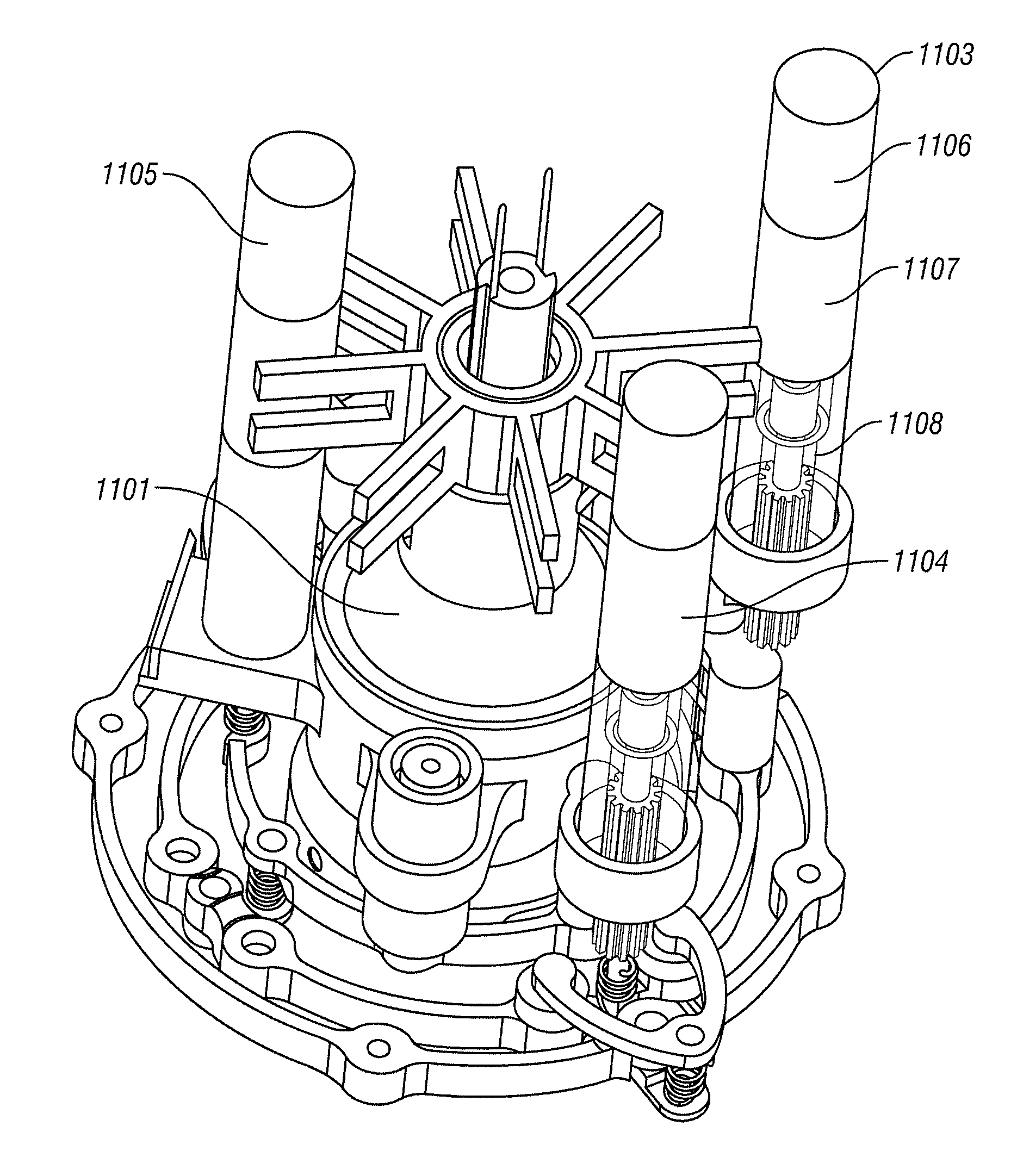
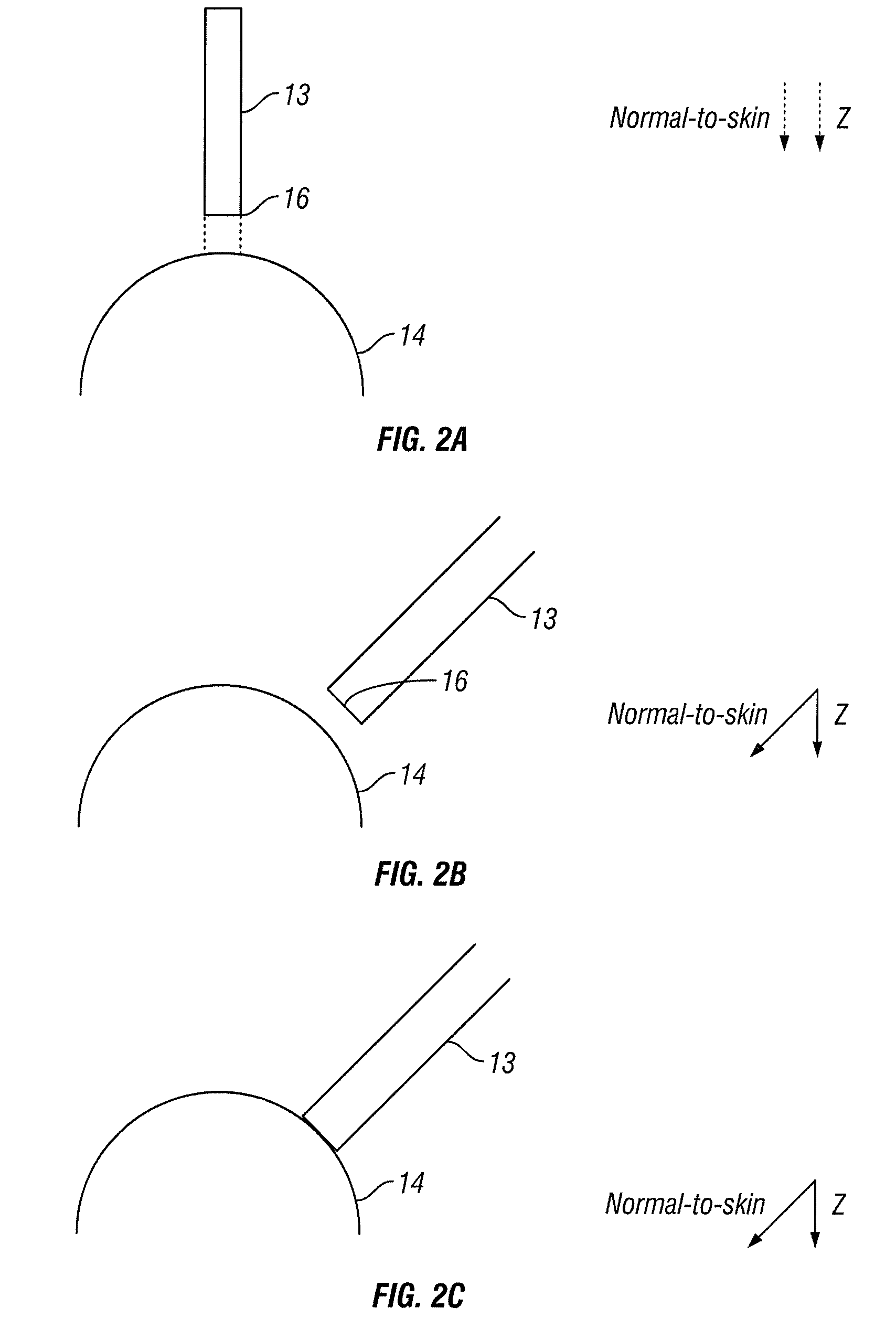
[0066]The invention comprises a noninvasive analyzer sampling module. Preferably the sample module controls position and / or attitude of a sample probe tip relative to a sample site. Optionally, the sample probe is controlled by an algorithm to minimally contact a sample site, tangentially contact a sample site and / or to controllably displace a tissue sample relative to the nominal plane of the sample tissue surface.

[0067]A key source of error in a noninvasive analyte property determination, such as a glucose concentration determination, is related to probe design and patient interface, as opposed to the spectrograph unit or algorithm design. A key parameter to control is the applied force or pressure applied by the sample probe to the interrogated tissue sample site. A force and / or displacement controlled sample interface aids generation of reproducible sample spectra used in conjunction with a noninvasive analyzer and algorithm to create acceptable reproducibility.

[0068]Preferably,...


PUM


Abstract

The invention relates generally to a probe interface method and apparatus for use in conjunction with an optical based noninvasive analyzer. More particularly, an algorithm controls a sample probe position and attitude relative to a skin sample site before and / or during sampling. For example, a sample probe head of a sample module is controlled by an algorithm along the normal-to-skin-axis. Preferably, the sample probe head is positioned in terms of 3-D location in the x-, y-, and z-axes and is attitude orientated in terms of pitch, yaw, and roll. Further, attitude of the probe head is preferably orientated prior to contact of the sample probe head with the tissue sample using indicators, such as non-contact distance feedback from capacitance sensor, contacting or non-contacting optical sensors, and / or contact electrical sensors.

Description

CROSS REFERENCE TO RELATED APPLICATIONS[0001]This application:[0002]claims benefit of U.S. Provisional Application No. 60 / 943,495 filed Jun. 12, 2007;[0003]is a continuation-in-part of U.S. patent application Ser. No. 11 / 625,752 filed Jan. 22, 2007, which is a continuation-in-part of U.S. patent application Ser. No. 11 / 117,104, filed Apr. 27, 2005, which claims the benefit of U.S. provisional application No. 60 / 566,568, filed Apr. 28, 2004; and[0004]is a continuation-in-part of PCT application No. PCT / US07 / 83497 filed Nov. 2, 2007, which claims benefit of U.S. provisional patent application no. 60 / 864,375 filed Nov. 3, 2006, all of which are incorporated herein in their entirety by this reference thereto.BACKGROUND OF THE INVENTION[0005]1 . Field of the Invention[0006]The invention relates generally to measurement of analyte properties in tissue. One embodiment relates to sample probe movement control in a noninvasive measurement.[0007]2 . Discussion of the Related Art[0008]Sampling...

Claims


Application Information

Patent Timeline
Patent Type & Authority Patents(United States)
IPC IPC(8): A61B5/00A61B5/1455A61B5/06A61B5/145
CPCA61B5/14532A61B5/6843A61B5/061A61B5/1455A61B5/14546
Inventor STIPPICK, TIMOTHY W.BLANK, THOMAS B.RUCHTI, TIMOTHY L.SLAWINSKI, CHRISTOPHER
Owner GLT ACQUISITION
Why Eureka
Try Eureka