Vacuum biopsy device

a vacuum biopsy and vacuum technology, applied in the field of vacuum biopsy devices, can solve the problems of unsatisfactory biopsy, high cost of vacuum creation, etc., and achieve the effects of improving cleaning effect, no twisting (turning), and good adhesion of sampl

Active Publication Date: 2005-09-15
CR BARD INC
View PDF99 Cites 224 Cited by
  • Summary
  • Abstract
  • Description
  • Claims
  • Application Information

AI Technical Summary

Benefits of technology

[0009] Starting with German Patent Publication No. DE 100 34 297 A1, which is considered to be the closest state of the art, the vacuum biopsy device for removal of tissue is based on the problem of configuring the hand piece so that the sample removal sequence can be operated with one hand after being inserted by means of a coaxial cannula, or with no such cannula. The advantages of the familiar high-speed biopsy gun without vacuum, namely, the quick penetration of the needle unit, carrying the sample removal chamber into the tissue being sampled, should be retained in addition to providing a vacuum generating device that is simple, reliable, and uncomplicated in structure. The removal of the sample should be such that the pathologist obtains a sufficient quantity of untwisted tissue for evaluation.

Problems solved by technology

In both biopsy mechanisms capable of removal of a sample under vacuum, the hand piece of the biopsy device is limited in its freedom of motion by at least one connection hose and / or supply cables to one or more external supply units; furthermore, the mechanisms for creating the vacuum are costly, especially in regard to the regulating mechanisms.
Such a positioning leads only to unsatisfactory biopsy results, especially when investigating hard tissue regions.

Method used


Image

  • Vacuum biopsy device
  • Vacuum biopsy device
  • Vacuum biopsy device

Examples


Embodiment Construction

[0055] The following detailed description should be read with reference to the drawings, in which like elements in different drawings are identically numbered. The drawings, which are not necessarily to scale, depict selected preferred embodiments and are not intended to limit the scope of the invention. The detailed description illustrates by way of example, not by way of limitation, the principles of the invention. This description will clearly enable one skilled in the art to make and use the invention, and describes several embodiments, adaptations, variations, alternatives and uses of the invention, including what is presently believed to be the best mode of carrying out the invention.

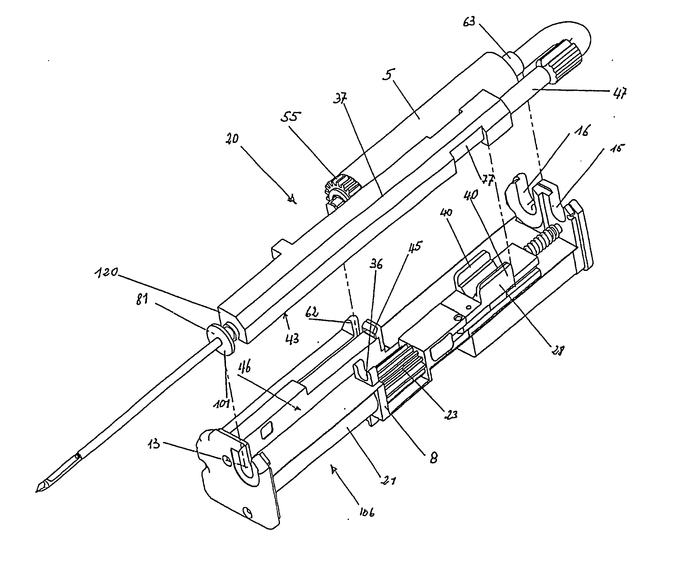
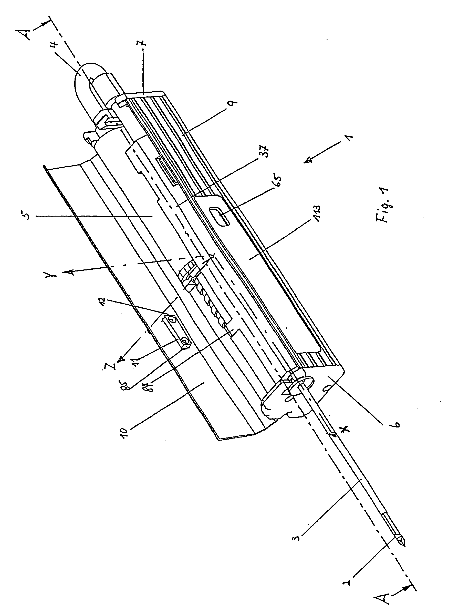
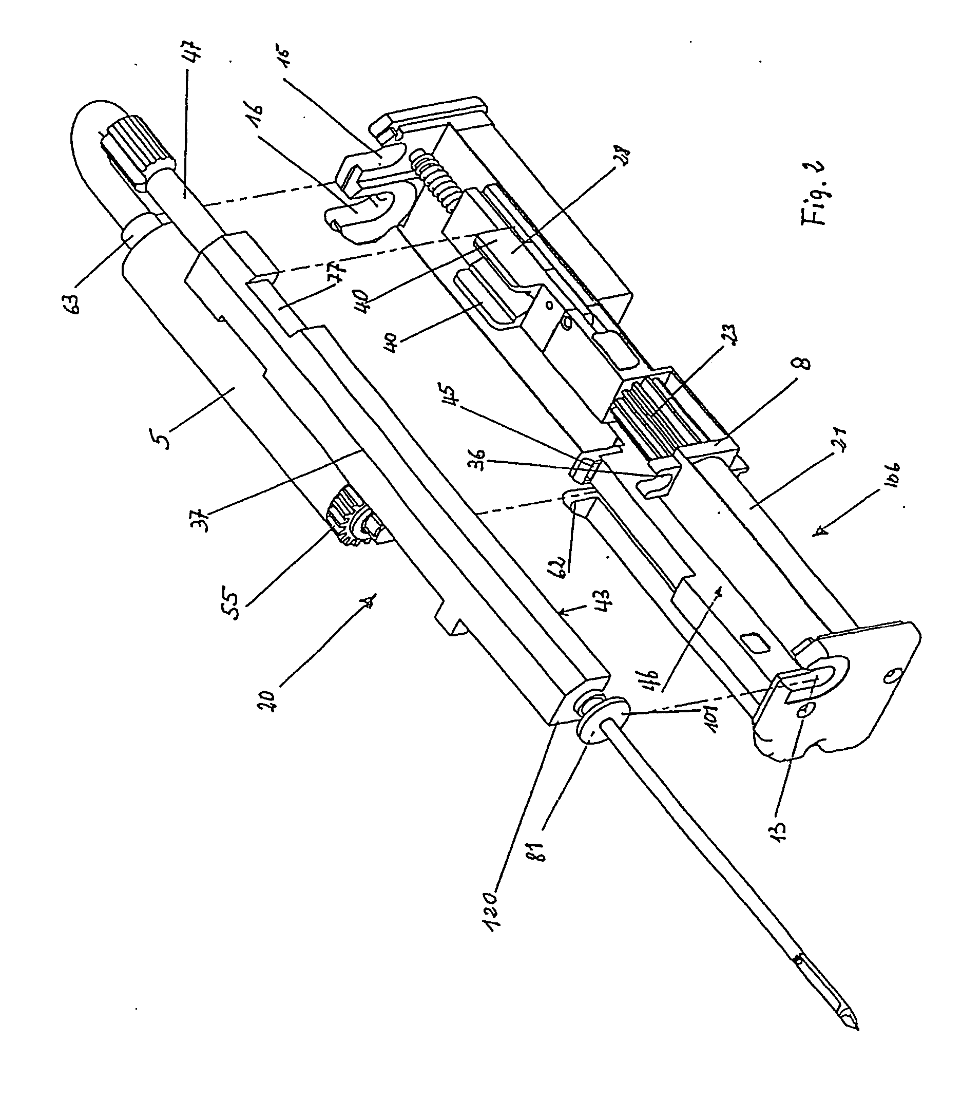
[0056] Integrated in the housing interior of a hand piece 1 are all devices required to perform a vacuum biopsy (FIG. 1), so that no cables or lines are required going from the housing of the hand piece to other external supply devices. Thus, the hand piece 1 constitutes a complete vacuum biopsy ...


PUM

PropertyMeasurementUnit
lengthaaaaaaaaaa
lengthaaaaaaaaaa
cocking distanceaaaaaaaaaa

Abstract

A biopsy device for taking tissue samples, includes a housing, a removable element and a control panel. The housing contains an electric power source and a tension slide connected to the power source. The tension slide may be brought into a cocked position against the action of a spring by the power source. The removable element is configured for insertion into the housing and includes a biopsy needle unit, a vacuum pressure-generating device and a control panel. The removable element may be provided as a sterile package unit. The biopsy needle unit can be arranged on the tension slide and includes a hollow biopsy needle with a sample removal chamber and a cutting sheath. The biopsy device can be held in one hand and is fully integrated with all components required to perform a vacuum biopsy such that no cables or lines are required to other external units.

Description

CROSS-REFERENCE TO RELATED APPLICATIONS [0001] This is a national stage application under 35 USC §371 of International Application PCT / DE03 / 00844, filed on Mar. 17, 2003, the entire contents of which are incorporated by reference herein.FIELD OF INVENTION [0002] The invention pertains to a biopsy device for taking of tissues samples, which consists of a hand piece, in which a hollow biopsy needle is inserted, wherein a portion of the biopsy needle protruding from the hand piece is introduced with its sampling chamber into the tissue being investigated and the tissue is sucked into the sampling chamber by vacuum and then separated by a sample separating mechanism and finally removed. BACKGROUND OF INVENTION [0003] A method and a device for cutting out tissue is already known from British Patent Publication No. GB 2018601A, in which the tissue in the biopsy needle is sucked into a cutting region under vacuum influence. In order to create a vacuum in the hollow needle, the hand piece i...

Claims


Application Information

Patent Timeline
Patent Type & Authority Applications(United States)
IPC IPC(8): A61B10/00A61B17/00A61B10/02A61B17/34A61B19/00A61M25/06A61M39/10A61M39/12G01N1/08
CPCA61B10/0233A61B10/0275A61B10/0283A61B17/3421A61B2010/0208A61B2017/00477G01N1/08A61B2017/00924A61B2019/306A61M25/065A61M39/1055A61M39/12A61B2017/00911A61B2090/036A61B90/03
Inventor HESKE, NORBERTHESKE, THOMAS
Owner CR BARD INC
Why Eureka
Try Eureka