Source grating for talbot-lau-type interferometer
a source grating and interferometer technology, applied in the field of source grating for use, can solve the problems of insufficient x-ray quantity to realize high-contrast imaging with high-energy x-rays for medical use, the source grating of wo2007/32094 may not produce the short-wavelength x-rays and high spatial coherence needed for medical use, and achieve high x-ray transmittance
- Summary
- Abstract
- Description
- Claims
- Application Information
AI Technical Summary
Benefits of technology
Problems solved by technology
Method used
Image
Examples
first embodiment
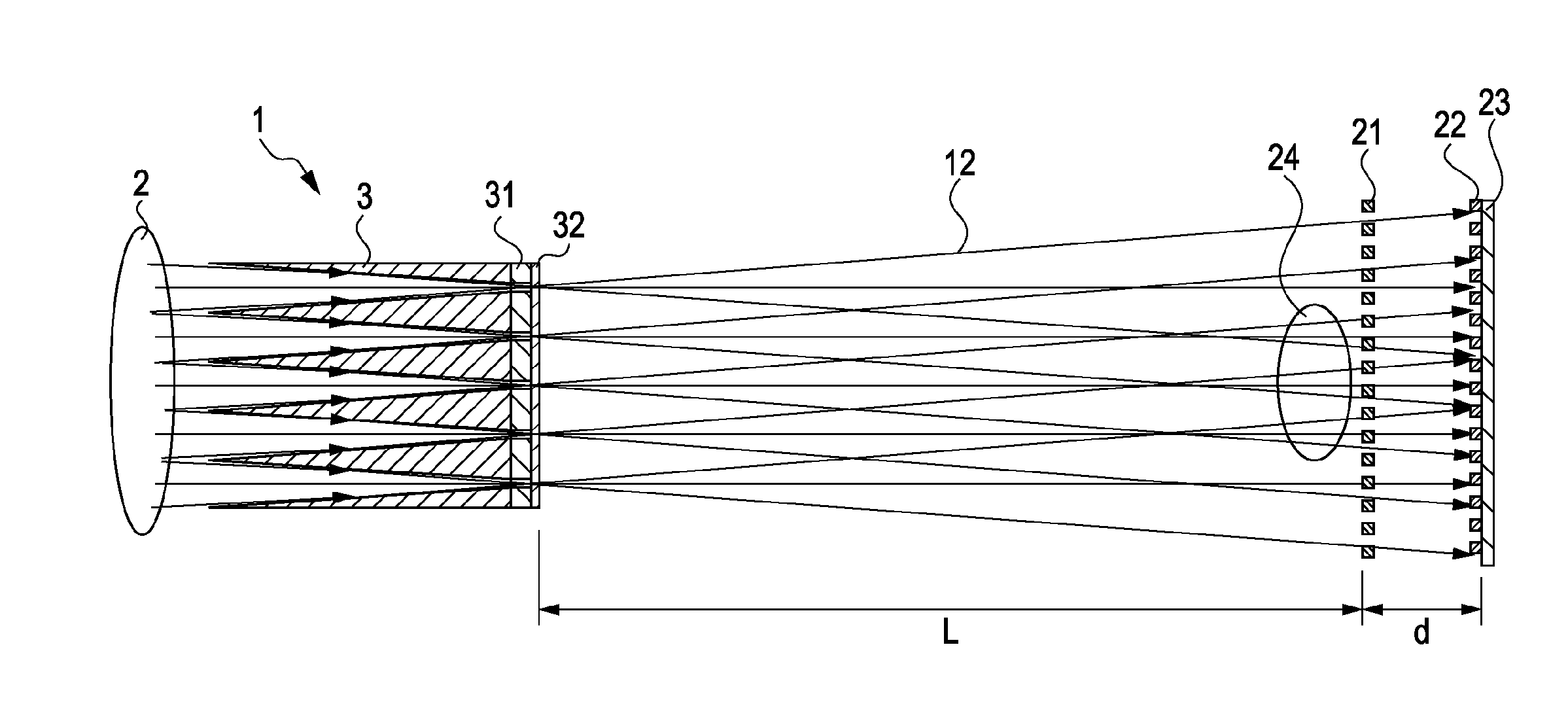
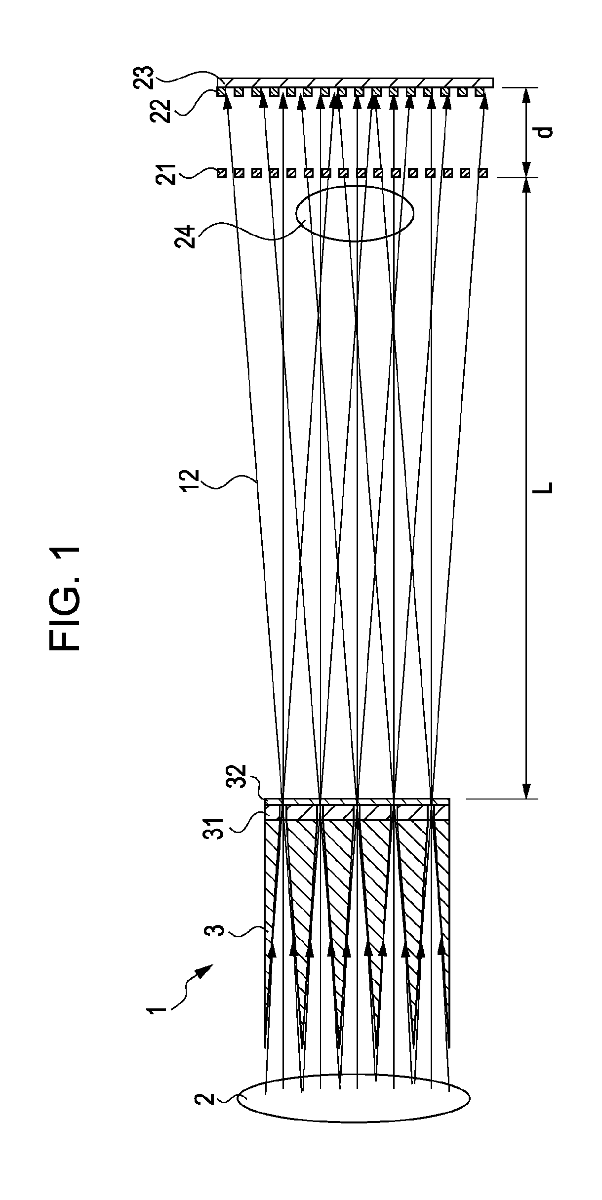
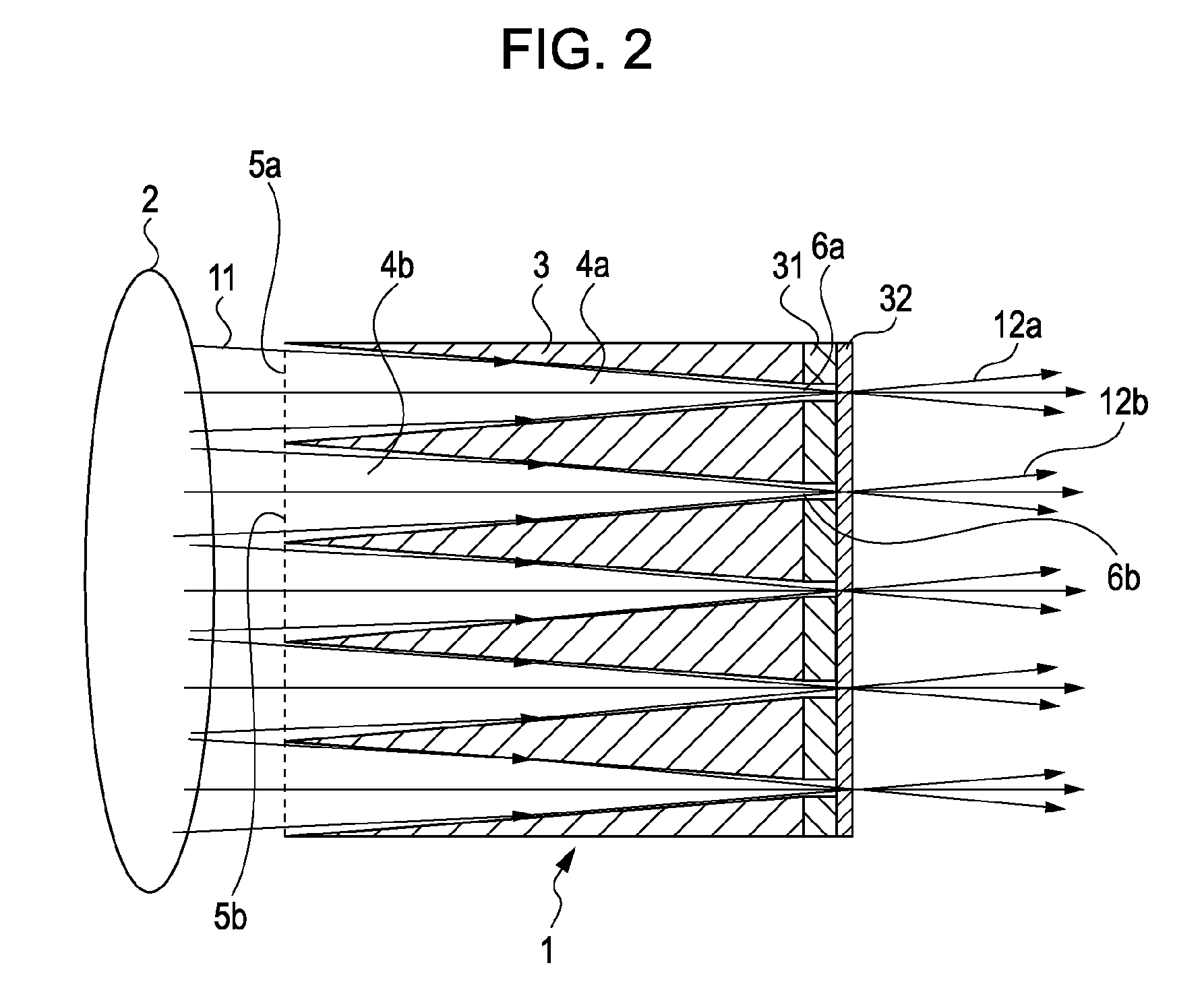
[0025]A source grating for a Talbot-Lau-type interferometer according to a first embodiment of the present invention will now be described with reference to FIGS. 1 to 3.
[0026]FIG. 1 illustrates a configuration of a Talbot-Lau-type interferometer of the first embodiment. Referring to FIG. 1, the Talbot-Lau-type interferometer includes a source grating 1, an X-ray source 2, a sample 24, a phase grating 21, an absorption grating 22, and an X-ray detector 23.
[0027]As shown in FIG. 1, the source grating 1 is located on an X-ray emitting side of the X-ray source 2. Although a detailed structure will be described below, the source grating 1 has apertures through which X-rays pass. X-rays emitted from the X-ray source 2 partly pass through the apertures of the source grating 1, and are applied onto the sample 24 or the phase grating 21.
[0028]The phase grating 21 is located at a distance L from the source grating 1 on a side opposite the X-ray source 2. In the first embodiment, the phase gr...
first modification
of First Embodiment
[0051]The shape of the incident apertures 5 of the channels 4 in the surface ABCD is not limited to a circular cross-section as illustrated in FIGS. 3A and 3B. For example, square incident apertures as shown in FIG. 5A may be provided based on specific application requirements. When circles are laid in a certain plane, spaces are formed between the circles. In contrast, squares can fill the plane with little space therebetween. Therefore, when the incident apertures are square, the ratio of the total aperture area of the incident apertures to the cross-sectional area of the surface ABCD can be higher than when the incident apertures are circular. Similarly, the shape of the exit apertures 6 can also be determined arbitrarily.
[0052]By increasing the ratio of the total aperture area of the incident apertures on the source side, more incident X-rays can be converged at the exit apertures. This further increases the transmittance.
second modification
of First Embodiment
[0053]In the above-described embodiment, the channels 4 in the guide tube 3 are two-dimensionally arranged, as shown in FIGS. 3A-3C or 5A-5B. In the source grating 1 of the present invention, channels 4 may also be one-dimensionally arranged, as shown in FIG. 6A. In a one-dimensional source grating 1 shown in FIG. 6B, channels 4 are arranged at a pitch Po in a direction of the short sides of the cross sections of the channels 4.
[0054]In the configuration of the Talbot-Lau-type interferometer shown in FIG. 1, a one-dimensional source grating may be used when the phase grating 21 is a one-dimensional grating, and a two-dimensional source grating may be used when the phase grating 21 is a two-dimensional grating. In the illustrations of FIGS. 5A-6B, the same numerical references as those of FIGS. 3A-3C represent similar functions. Thus, description thereof has been omitted for brevity.
PUM
 Abstract
Description
Claims
Application Information
 - R&D
- Intellectual Property
- Life Sciences
- Materials
- Tech Scout
- Unparalleled Data Quality
- Higher Quality Content
- 60% Fewer Hallucinations
Browse by: Latest US Patents, China's latest patents, Technical Efficacy Thesaurus, Application Domain, Technology Topic, Popular Technical Reports.
© 2025 PatSnap. All rights reserved.Legal|Privacy policy|Modern Slavery Act Transparency Statement|Sitemap|About US| Contact US: help@patsnap.com


